gooブログはじめました!

写真付きで日記や趣味を書くならgooブログ

MDI TIS2web Pass-Thru Programming Guide

2020-02-02 10:16:26 | 日記

Pass-thru programming requires that the GM MDI remain connected to the terminal and to the vehicle throughout the programming process. The vehicle must be in close proximity to the terminal while using pass-thru programming.Here car-auto-repair.com share the guide on how to use MDI TIS2web to perform Pass-Thru Programming.


Note:TIS 2 Web only supports Pass-Thru Programming with the MDI.


Pass-Thru Programming Procedure


1.Launch TIS 2 Web.


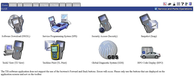
2.From the TIS 2 Web main screen


MDI-TIS2web-Pass-Thru-Programming-Guide-1


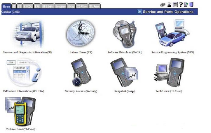
Select the Service Programming System icon.


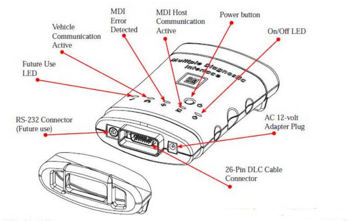
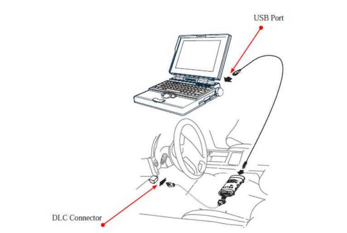
3.Connect MDI to vehicle


MDI-TIS2web-Pass-Thru-Programming-Guide-2


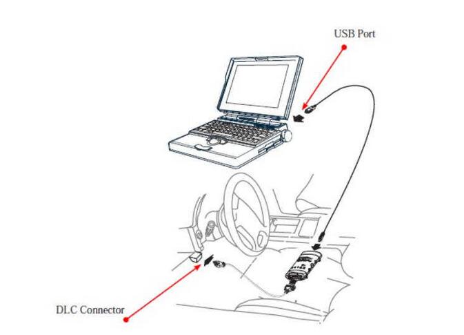
And Display device (e.g. PDA, PC screen)


MDI-TIS2web-Pass-Thru-Programming-Guide-3


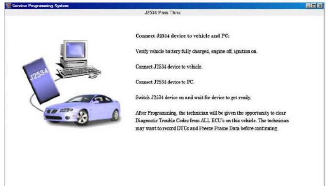
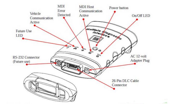
Power On MDI using ON/OFF button.


MDI-TIS2web-Pass-Thru-Programming-Guide-4
Key on, battery fully charged.


Select “Start SPS”.


MDI-TIS2web-Pass-Thru-Programming-Guide-5


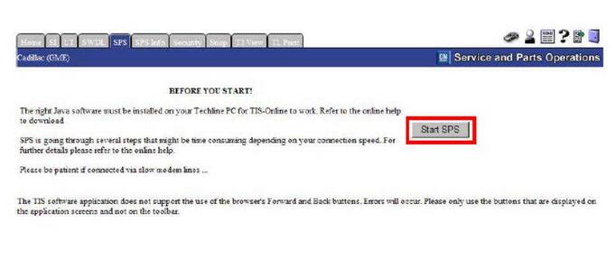
SPS software version will appear on the screen.
MDI-TIS2web-Pass-Thru-Programming-Guide-6


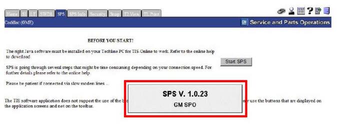
If hardware screen does not appear, check software connections. This process could take some time depending upon you internet connection.


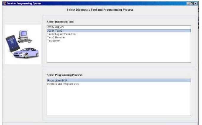
Select Diagnostic Tool J2534 GM MDI.


MDI-TIS2web-Pass-Thru-Programming-Guide-7
Select Programming Process.


MDI-TIS2web-Pass-Thru-Programming-Guide-8


4.Select “Next” to “Sales Make” screen.
MDI-TIS2web-Pass-Thru-Programming-Guide-9
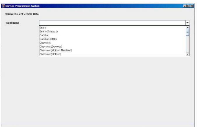
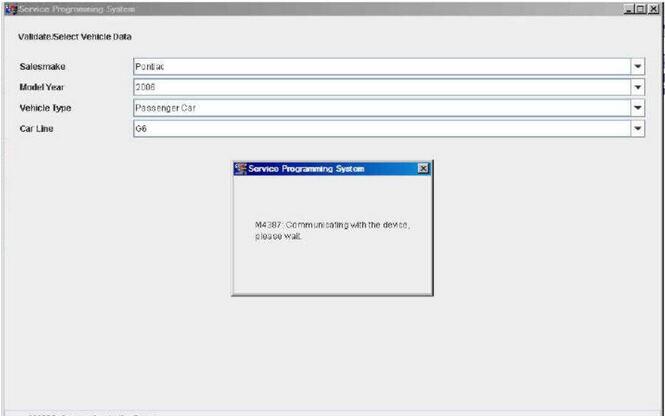
Complete all terminal directed data until “Next” is highlighted (vehicle data will vary). Select “Next.” You may or may not get a pop-up screen.
MDI-TIS2web-Pass-Thru-Programming-Guide-10
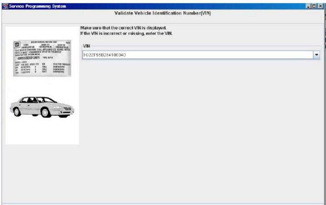
Make sure correct VIN is displayed. If VIN is incorrect or missing enter the correct VIN .
MDI-TIS2web-Pass-Thru-Programming-Guide-11
Note:In order to reduce the potential for signal loss. The MDI should be configured for the most stable communication option at your location. You can choose from USB, Ethernet, or Wireless Ethernet.


5.At the “Supported Controllers” screen:
MDI-TIS2web-Pass-Thru-Programming-Guide-12
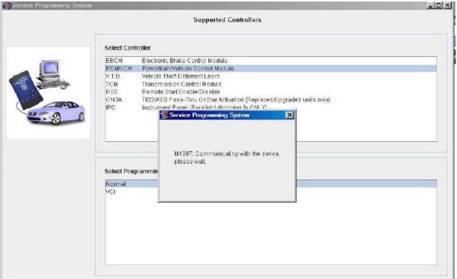
Select the appropriate control module under “Select Controller,” e.g. PCM / VCM Control Module etc.
Select the appropriate programming type (Normal, VCI).
MDI-TIS2web-Pass-Thru-Programming-Guide-13
Select Next. For VCI you will need to contact your local Customer Support Center


IMPORTANT


When selecting the vehicle configuration index (VCI) programming type, a valid VCI number for the vehicle must be entered. This number may be obtained from the Techline Customer Support Center.


The correct tire size and axle ratio must be highlighted and a valid VCI number entered if you select Reconfigure for your programming type.


Select Cancel if you receive a message stating that the calibration selected is already the current calibration in the control module and reprogramming with the same download is not recommended.


6.During communication a “validate /select vehicle data” screen will appear.
MDI-TIS2web-Pass-Thru-Programming-Guide-14
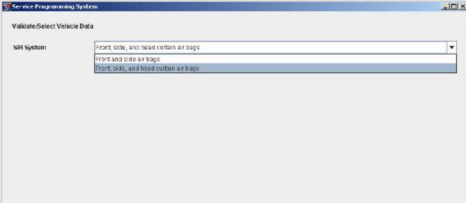
You may or may not get a popup screen.
MDI-TIS2web-Pass-Thru-Programming-Guide-15
7.At the Calibration Selection screen:


Select the appropriate calibration(s).
MDI-TIS2web-Pass-Thru-Programming-Guide-16
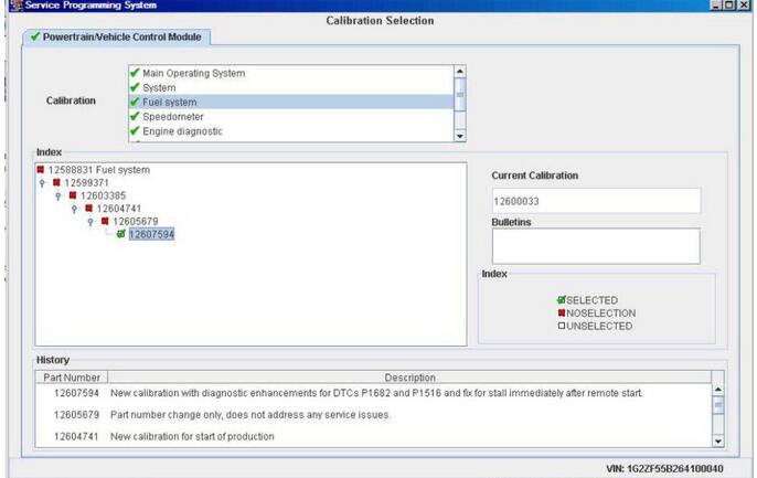
Make sure all folder tabs have a green check mark.


Select Next.


8.At the Summary screen:
MDI-TIS2web-Pass-Thru-Programming-Guide-17
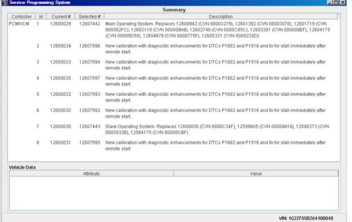
Verify current calibration(s) with selected calibration(s).


Select Next.


At the Summary Screen, current calibration is displayed along with the new calibrations available for the selected vehicle. Diagnostic enhancements are listed for various DTC’s. Multiple screens may be available. Calibration data may be printed from these screens.


The Transfer Data screen appears as reprogramming begins, finishing when the percentage bar reaches 100 percent. Time may vary depending upon calibration.
MDI-TIS2web-Pass-Thru-Programming-Guide-18
Estimated remaining programming time will appear on the screen.


IMPORTANT


Some vehicles will require that Idle Learn, TP Learn, Theft Deterrent Relearn, or Crankshaft Variation Learn procedures be performed after programming. Consult the appropriate service information for these procedures.


9.The Program Controller “Programming Complete” screen appears.
MDI-TIS2web-Pass-Thru-Programming-Guide-19
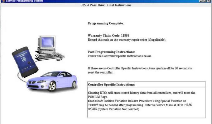
10.Select “clear DTC’s” to erase history data. The program will return to the TIS 2 Web main screen. Be sure to verify successful reprogramming.


A warranty claim code will appear if appear if applicable.


A calibration module replacement must be changed on the vehicle for the claim code to appear. These may be “Post Programming” and or controller specific instructions after programming is completed.


At the summary screen, current calibration is displayed along with the new calibrations available for the selected vehicle. Diagnostic enhancements are listed for various DTC’s. Multiple screens may be available. Calibration data may be printed from these screens.


11.Turn off the MDI by pressing the ON/OFF button. Select Cancel.


MDI-TIS2web-Pass-Thru-Programming-Guide-20


12.Disconnect the MDI from the vehicle for disconnect.
MDI-TIS2web-Pass-Thru-Programming-Guide-21


Verifying Reprogramming


After any kind of control module programming, verify that programming was successful:


Turn the ignition off, wait at least 30 seconds, then start the vehicle to confirm that reprogramming was successful. If the vehicle does not repeat the SPS procedure.


How to Program an Electronic Control Module (ECM) with GM SPS

2020-02-02 10:11:13 | 日記


How-to-Program-an-Electronic-Control-Module-(ECM)-with-GM-SPS

The Service Programming System (SPS) is a PC application that updates (programs or reprograms) the flash calibration files that are stored in a vehicle’s ECM. To do this, the application reads VIN information from the vehicle, extracts the correct update data from the SPS application’s data files, then updates the vehicle reprogrammable memory with the data.


How-to-Program-an-Electronic-Control-Module-(ECM)-with-GM-SPS


Electronic Control Module (ECM) Programming with GM SPS


1.Turn the vehicle ignition to the ON position (do not start the engine).


2.From the Windows desktop, double-click the TIS 2000 icon. This displays the TIS 2000 – Application Selection window.


3.Click the Service Programming System icon to start the SPS application. This displays the SPS System’s Select Diagnostic Tool and Programming Process window.


4.Select the following:


a) In the Select Diagnostic Tool area, select Pass-Thru.


Note: The Information Only/PROM Data option displays PROM or calibration data for a vehicle.


b) In the Select Programming Process area, select one of the following:


Select Reprogram ECU to reprogram (reflash or calibrate) the selected ECM (ECU).
Select Replace and Program ECU to program a new ECM.


c) In the Select ECU Location area, select Vehicle.


Note: The OBPA option applies only if an off-board programming adapter (J41207-C) is available for the Tech 2 Flash.


d) Click the Next button to continue. This displays the Determine Vehicle window.


5. Do the following on this window:


a) Skip the VIN area. It is not necessary to enter a VIN.


b) In the Vehicle Data area, for each item, click the down arrows (at the right side of each line) and select the correct options for the vehicle salesmake, model year, vehicle type, car line, and engine type(s).


c) When finished, click the Next button. This displays a connection instructions


6. Do the following:


a) Follow the instructions on the window. Double-check the following:


For the Tech 2 Flash, press the power key to turn on the Tech 2 Flash and then make sure it displays the version number screen.
For the Next Generation scan tool, press the power key to turn on the scan tool and then select GM SPS Reprogramming. Set the baud rate for the PC by selecting CONFIGURATION > I/O management > Pass-thru > Properties > Baud >38400, 57600, or 19200 (whichever works best) >OK. Use Exit to return to the Service Programming screen. Then make sure the scan tool displays the GM Reflash Pass-Thru Mode screen.


CAUTION: Do not change the baud rate after starting the programming process.


Make sure the vehicle key is in the run position and the battery is fully charged. It is permissible to use
a) booster pack, but not a battery charger!
b) Click the Next button to continue.


7. An SPS warning message may appear to warn that you must input the VIN number. If so, click the OK button to continue. This displays the Validate VIN window.


8. Verify the VIN that is automatically read from the vehicle (compare it to the vehicle VIN plate) or manually enter the VIN. Then click the Next button to continue. This displays the Supported Controllers window.


Note: If an option window appears, enter all of the information required and then click the Next button to continue. Also, if you need to enter a VCI number, a message appears to tell you so.


9. On the Supported Controllers window, do the following:


a) In the Select Controller area, select the controller to program.


b In the Select Programming Type area, follow these steps:


First, select Normal to update an existing calibration or to program a new controller.
If a VCI number is required, contact your dealer. Once the VCI number is obtained, select VCI (Vehicle Configuration Index) under Select Programming Type to update an existing calibration or to program a new controller on new vehicles for which the VIN code is not yet in the SPS database. Also select VCI under Select Programming Type to program (calibrate) a vehicle for a different transmission or to calibrate the speedometer for changed tire size or axle ratio.


Note: The Reconfigure selection is not supported for all vehicles, it is not recommended to choose this selection.


c) Click the Next button to continue. Depending on which controller and programming type you entered, this displays either the Calibration Selection window or a a dialog box requesting more information (reconfigure information, a part number, or the VCI number).


10. If you selected a controller that requires additional information, an information request dialog box appears.If this dialog box appears, do the following.(Otherwise, skip this step.)


a) Obtain the required information using the Tech 2 or Next Generation scan tool as follows:


If you are using the Tech 2 scan tool for the passthru procedure, exit the procedure and use the scan tool to scan the vehicle and request the module (controller) information.


If you are using the Next Generation scan tool for the pass-thru procedure and have the GM Reflash Pass-Thru Mode screen displayed, press the Enter key to display the list of controllers. Select the controller from the list and press the Enter key to display the module (controller) information.Note the required information and press the Enter key again to return to the Pass-Thru Mode.
b) Select the correct value from the drop-down list and then click the OK button to continue.


Note: If the correct value is not in the list, do not program the controller; exit this procedure.


11. If you selected VCI as the programming type,a dialog box appears for entering the VCI number. If this dialog box appears, do the following.(Otherwise, skip this step.)


a) Enter the VCI number into the VCI box.


Note: If there is a ZERO (0) in the box, delete it before entering the VCI number.


b) Click the OK button.


12. View the calibration file history descriptions for the controller being programmed; for example, Powertrain (PCM) or Vehicle Control Module (VCM). Select the file(s) for updating the controller as follows:


a) Use the following information to determine which file(s) to select:


Vehicles with PCMs display as a single “tab” that summarizes all calibration files for the vehicle.
Vehicles with VCMs display as multiple “tabs” – one for each distinct calibration file contained in the VCM. A selection must be made under each tab to successfully select the programming files.


The window lists valid calibrations for the VIN entered. Selecting the right calibration is critical. Check the history of each calibration.The history lists an explanation of the calibration file, telling what the calibration is for and whether it supersedes any other calibrations. Related bulletin numbers are sometimes listed along with the calibration files. Read the latest bulletins to stay up to date on why certain calibrations have been released. Based on the history and bulletins, select the appropriate calibration file.


Note: If calibrations are the same, the NAODRUI Control box appears (Figure 2.21) stating that the calibrations selected are already the current calibrations in the control module. Click OK and Back out or click Cancel on the Summary screen.


Important:


Before continuing, consult any service bulletins identified for the calibration and follow all specific steps before beginning the programming.
b) Click the appropriate box(es) to select the calibration file(s).
c) Click the Next button to continue. This displays the Summary window.


Note: If a warning message appears about the Tech 2,follow the instructions and then click the OK button


13. The Summary window displays a summary of calibration selections that are about to be programmed to the controller. Confirm the selections and click the Next button to begin the programming.


14. One or more warning message boxes may appear. If so,follow any instructions they provide and click the OK (or YES) button on each one to continue the procedure. Do this until the Transfer Data window appears