goo blog サービス終了のお知らせ 

くっしーの徒然日記

無線、天文、修理、剣道、体調他について書いてます。修理や改造記事のマネに関してはあくまでも自己責任にてお願いします。

(tr)uSDX 感度測定

2023-05-22 | アンテナ・無線機(修理)
先日買った(tr)uSDXであるが、買う前に「きっと感度的にはKX2とかにかなわないだろうな」と思いしばらく購入を控えていた。7MHzは何とかなるだろうけど、ハイバンドは厳しいだろうなと思っていたが、いくら考えても答えは出ないので、人柱のつもりで買って、自分で測るしかないかなと思って購入した次第である。
I bought the (tr)uSDX the other day, but before I bought it, I thought, "I'm sure it won't be as good as the KX2 in terms of sensitivity," so I refrained from buying it for a while. I thought 7MHz would be good, but the high band would be bad. I thought I had no choice but to buy it myself and measure it myself.

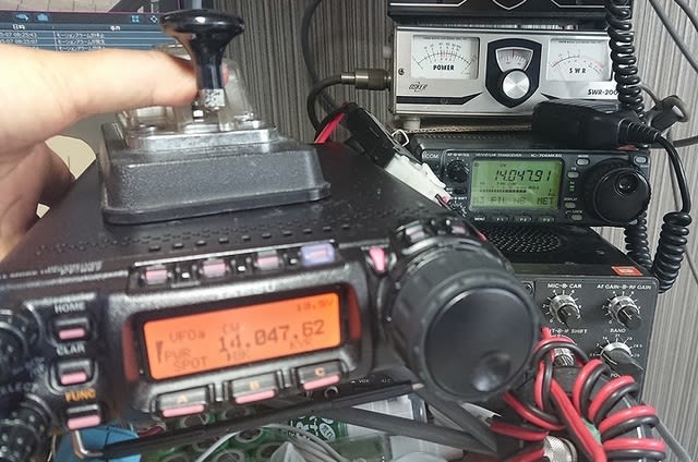
↓せっかくなので、手持ちのKX2、FT-817と比較で測定してみた。

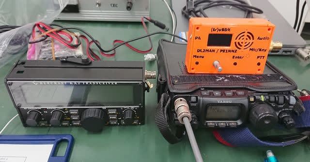
↑I measured it by comparing it with my KX2 and FT-817.

各無線機の感度スペックは下記の通りである。
The sensitivity specifications of each radio are as follows.

FT-817:10dBS/N時で、0.25μV=0.5μVemf=(-113dBm-6dB)=-119dBmJAIA規格
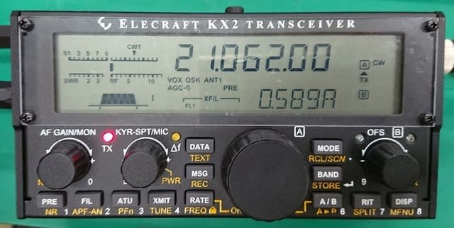
KX2:3dBS/N時で、Typ.-136dBm@3dBS/N:BW=500 ARRL規格
(tr)uSDX:記載なし

FT-817: @10dBS/N, 0.25μV=0.5μVemf=(-113dBm-6dB)=-119dBmJAIA standard
KX2:Typ.-136dBm@3dBS/N:BW=500 ARRL standard
(tr) uSDX: not mentioned

ちなみに、817はフィルター無し時の規格だ。
817 is the standard without filter.

またJAIA規格は、CW/SSB共通で10dBS/N時の値となっているが、10dBS/NだとSSBでRS41~51位の了解度と考えて貰って良いだろう。
In addition, the JAIA standard is the value at 10dBS/N for both CW/SSB. At 10dBS/N, the RS is about 41 to 51 in SSB.

ARRLの3dBS/Nは、完全にCWがデコードできるレベルで耳で聞いてRST529位。
ARRL's 3dBS/N is at a level where CW can be completely decoded, and by ear it RST529.

実際に測定してみると1dBS/N時で十分聞き取れる。419~519位だろうか。
When I actually measured it, it was RST419-519 at a level that I could hear well at 1dBS/N.

↓と言う事で、3台を順に測定してみた。

↑I tried to measure 3 sets.

SP端子の1dBS/Nを見る為には、デジタルの測定器は使いにくかったので、(tr)uSDX以外はアナログの針式メータのついている測定器で測定した。
It was difficult to use a digital measuring instrument to measure 1dBS/N at the SP terminal, so I used a measuring instrument with an analog meter, except for (tr)uSDX.
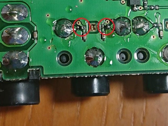
↓(tr)uSDXのSP出力波形

↑(tr) uSDX SP output waveform

ただ、(tr)uSDXはSP端子から78KHz位の信号が漏れており、これでは測れなかったので、8903Bにて、CCIT(聴感フィルター)フィルターで78KHzを除去して測定した。
However, (tr) uSDX leaked a signal of about 78 KHz from the SP terminal, so I could not measure it with this, so I used 8903B to remove 78 KHz with a CCIT (sophometric filter) filter.

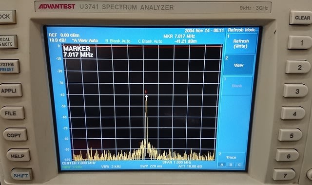
↓それぞれを測定した結果は以下の通り。(拡大画像)

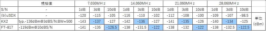
↑ The results of each measurement are as follows.(Zoom UP)

思ったよりも(tr)uSDXは悪い事が判った。概ね20dB以上悪い値だ。全てBW=500Hz。
(tr) uSDX was generally worse than 20dB.(All sets are BW=500Hz)

7MHz辺りを実際に自宅で聞き比べた感じでは、IC-7300に比べて1~3dB位悪いかなというレベルで、7300でギリギリ聞こえる信号こそ聞こえないが、7300で519位の信号は(tr)uSDXでも聞こえる。(ALL JAコンテストで色々なレベルの局を聞き比べた)

When I listened to and compared 7MHz at home, it was about 1 to 3dB worse than the IC-7300.
I can't hear the barely audible signal on the 7300. However, the signal at position 519 on the 7300 is also audible on (tr)uSDX. (Listened and compared at the ALL JA Contest)

色々と考えてみたが、どうも(tr)uSDXはトータルゲイン、特にANT~ADCまでのゲインが不足しているのが原因と思われる。KX2や7300のブロックダイヤを確認しても、ADCに入れる前にみんなアンプが入っているが、それがついてないのが原因だろう。

I thought about it, but it seems that (tr) uSDX lacks the total gain, especially the gain from ANT to ADC. Even if you check the block diagrams of the KX2 and 7300, they all have an amplifier before the ADC. (tr) uSDX is probably because there is no amplifier.

なので、SGを使った低ノイズ時の感度は悪いが、自宅等のノイズレベルが高い環境では、普及機に比べて少し悪い位で受信できるという感じだ。

Therefore, the sensitivity is poor when using SG for low noise, but in an environment with a high noise level such as at home, it seems that reception is slightly worse than that of popular models.

ハイバンドに行くほど、自宅でもノイズレベルは下がってくるのでその差は開いて行きそうだが、今の所、ハイバンドではコンテストでもギリギリ受かる信号を比較できるほど、沢山の局が受からないので、比較できていない。

The higher the band, the lower the noise level even at home, so the difference is likely to widen, but so far, the high band doesn't have enough signals to compare with the signals that barely pass the contest, so I can't compare.

この辺を定量的に測定できる規格を私は良く知らないのだが、疑似音声信号(ほぼホワイトノイズ)でSGをFM変調して、2信号で加えてあげると、定量的に測定が出来るだろうか?

I'm not familiar with the standard that can quantitatively measure this characteristic, but if I FM-modulate the SG with a pseudo-speech signal (almost white noise) and add the two signals, would it be possible to get a close measurement?

そのうち気が向いたらやってみるか、、、、
I'll give it a try when I feel like it

山でのノイズ環境でどの程度まで使えるのか?
To what extent can it be used in a noisy environment in the mountains?

とりあえず、LNAでも組み込まないとハイバンドで使うのは厳しそうだなぁ。
It seems to be difficult to use in the high band unless an LNA is incorporated.

2023.04.27 (5/22 UP)

PS.2023/10/11:
   1)測定時のフィルター条件は、3台ともBW=500Hzに統一してある。
   2)FT-817とKX2では1dBS/N時、3dBS/N時ともに概ね2~4dB程度
     KX2の方が感度が良い。

   1) Filter conditions are BW=500Hz for all three sets.
   2) The sensitivity of KX2 is 2 to 4 dB better than FT-817.
     Both at 1dBS/N and 3dBS/N

KX2再修理;ATU動作不良、HI CUR 表示、POW出ず

2023-01-05 | アンテナ・無線機(修理)
さて、12月25日の峠山移動で相変わらず不具合が残っている事が発覚したKX2。自宅で再現試験をすると、「HI CUR」は出ない物の、TUNE後にVS=1.0~2.5位を示すのに、パワー表示もパワーもまるっきり出ない時とパワー表示は出るが、実際のパワーは出ない時と、普通に表示もパワーも出る時も有る。
On December 25th, the KX2 was discovered to have a problem as usual when it moved to Mt. Toge. When I test at home, "HI CUR" is not displayed. However, after TUNE, VS=1.0 to 2.5 is shown, but the RF display is not displayed and the actual power is not output. Sometimes the RF display is displayed but the actual power is not output. Sometimes the RF display is also displayed and the actual power is also output.

↓ATU動作、VS1.0表示後の送信。LCD表示も振れなければ、実際のパワーも出ない。

↑Push ATU, show VS1.0. Then TX. No RF display. No actual power output.

↓ATU動作、VS2.3表示後の送信。LCD表示は振れてるが、実際のパワーは出ない。

↑Push ATU, show VS2.3. Then TX. LCD show RF display. But No power.

色々な症状が出たり出なかったりで、原因特定には結構時間が掛かりそうな感じ。
Various symptoms appear and disappear, and it seems that it will take quite some time to identify the cause.

IC-705でも買って当面SOTAに使い、KX2はじっくり修理しないとダメかなぁ。
I think I'll have to buy an IC-705 and use it for SOTA for the time being, and then carefully repair the KX2.

調べるとIC-705は今部品不足か、在庫が有るお店が殆どなく入荷待ち状態。
However, IC-705 is out of stock any stores and waiting for arrival.

暫らくFT-817だけと言うのもつらいので、壊れている所をじっくり確認して修理するのを諦めて、手っ取り早く治す方法がないか、ネットを調べてみた。

It would be a shame to just use the FT-817 for a while, so I gave up trying to find out what was broken and repaired it, and searched the net for a quick fix.

「HI CUR」で調べると、やはりATU不調で「HI CUR」が出ると言う書き込みを発見。
I checked with "HI CUR". I also found a post saying "HI CUR" due to ATU malfunction.

周りの助言は内部のアンテナコネクタの接触不良や断線等で繋がって無いと「HI CUR」がでる、との事。

The advice is that "HI CUR" will appear if it is not connected due to poor contact or disconnection of the internal antenna connector.

このスレの最終結論は、コネクタを確認したが変化なしで、メーカに修理に出した所、U20/U22のドライバーICを交換したとの事。

The final conclusion of this thread is that the connector has been checked, but there is no change. He sent it to the manufacturer for repair and replaced the U20/U22 driver IC.

またしてもドライバーICですか!!
Driver IC again! !

しかもよく読むと、回路図に載ってるシレンザのSGA-7489をミニサーキット社のGali 84+に交換している!!

Moreover, the SGA-7489 of Silenza on the schematic is replaced with Gali 84+ of Mini Circuits! !

たしかに、前回Groupes.ioの書き込み時にもドライバーの仕様が変更されているとのくだりが有ったがこの事か。

Indeed, Last time Groupes.io was written, it was written that the driver specifications had changed. Was this the case?

↓シレンザ社のSGA-7489


↓ミニサーキット社のGali 84+


データシート上では余り大きな差はない様に見える。Typ値は7489が多少良いが、min値はGaliが良い。Galiの方がばらつきが少ないって事?あまり大差無い様だが、、、

The datasheet doesn't seem to make much of a difference. 7489 is slightly better for the Typ value, but Gali is better for the min value. Gali has less variation? It doesn't seem like much of a difference, but...

ただ、Aliで売ってる値段は、7489が10個で1~1.5k円位に対して、Galiが1個で0.5~0.7k円と5倍以上の価格がする。価格が高い物だと、Aliでは偽物に引っ掛かる確率も上がるから嫌だなぁ、、

However, the price sold on Ali is 1 to 1.5k yen for 10 pieces of 7489, and 0.5 to 0.7k yen for 1 piece of Gali, which is more than five times the price. If the price is high, buy it on Ali, the probability of encountering a fake things will increase, so I don't like it,,,

メーカー修理に出したスレでは、7489がディスコンで変更と書かれてる。確かにWEBを調べると、7489はディスコンの様だ。

In the thread sent to the manufacturer for repair, it is written that 7489 has been changed due to discontinuation. Certainly, 7489 seems to be discontinued when I check the WEB.

取り敢えず、Gali 84+は手配したが、直ぐには手に入らない。
I ordered Gali 84+, but I can't get it right away.

当分の間は手持ちの7489で修理するしかない。
I have no choice but to repair it with my 7489.

一応セットをばらして、コネクタ周りの確認と先日交換しなかったドライバーと交換した方も念のため再交換する事にした。

I decided to disassemble the set, check around the ANT connector, and replace both driver ICs again.

↓先ずはセットをばらす

↑First, disassemble the set

BNCの芯線側はATU基板と近く、すぐ当たりかなり折れ曲がっている。
The center line of the BNC is close to the ATU board, and it hits immediately and is bent considerably.

↓熱収縮チューブを開いて中を確認。大丈夫の様だ。

↑Open the heat shrink tube and check inside. Its OK.

↓基盤に当たらない様に芯線金属を短くカットして再配線。

↑Cut the core metal short so that it does not hit the board and re-wire.

↓芯線を外したついでにBNCコネクタを外し、アース用の端子を取り付ける。

↑In addition, remove the BNC connector and attach the ground terminal.

これなら、オプションの小型バナナプラグが無くてもCPをケースGNDに接続できる。
With this, CP can be connected to case GND without the optional small banana plug.

↓ファイナル出力側のT5が銅テープに当たっているので、念の為テープで絶縁する。

↑Since T5 on the final output side is in contact with the copper tape, insulate it with tape.

放熱を兼ねている?とも思ったが、合成部トランスじゃないので余り熱は出ないだろう。

Does it also dissipate heat? I thought that too, but since it is not a combine transformer, it will not generate much heat.

↓上が当たっているT5。下が前回交換したドライバーの片割れ、部品面側のU20。

↑T5 where the upper side. The lower is one half of the driver that was replaced last time, U20 on the part side.

↓こちらが前回交換しなかった半田面のドライバーU22。(外して清掃・予備半田した所)

↑This is the driver U22 on the solder side that was not replaced last time. (Removed, cleaned and pre-soldered)

↓あと、ATUのANT出力コネクタの半田付けが甘かったので、念の為追加半田した。

↑Also, the soldering of the ATU's ANT output connector was loose, so I soldered it.

上記ドライバーを2個交換して、他のANTコネクタも確認。上記以外は問題は無かった。

Replace the above two drivers and check other ANT connectors. Other than the above, there were no problems.

と言う事で元通り組上げる。
Reassemble as before.

後で気が付いたが、ATUの取説を見るとATU基板の取り付け取り外しは、ファイナル側の側板を外して、横から8pinコネクタの刺さり具合を見ながら組み付けて、その後で側板を取り付ける手順になっていた。どうりで側板着いたままじゃ8pinコネクタが見えず前回組み付けに苦労した訳だ。

I noticed later, but when I read the ATU manual, the procedure for attaching and detaching the ATU board is to remove the side plate on the final side, assemble it from the side while checking how the 8-pin connector sticks, and then attach the side plate. there is No wonder I had a hard time assembling it last time because I couldn't see the 8-pin connector while it was still attached to the side plate.

まあ、今回は前回の苦労が有るので側板が付いたまま、なるべく内側に差し込むようにして無事に取り付けられたが、、、

Well, this time I had a hard time last time, so I was able to install it safely by inserting it inside as much as possible with the side plate still attached.

↓と言う事でくみ上げ後の、試験。一応問題なく動くしパワーも出る様だ。
KX2's ATU and TX operation after repair↑

これで一応ちゃんと動く様になったが、不安定な動作の根本原因を追究確認していないので、完全に治ったかどうかはちょっと自信がない。後は実践で使ってみて様子を見る様だろうか、、、

With this, it started to work properly, but I haven't investigated and confirmed the root cause of the unstable operation, so I'm not confident if it's completely cured. After that, I wonder if I'll actually use it in the field and see how it goes...

しかしこのドライバ2個の交換で治るとすると、一体何が起きているのだろうか?ドライバの増幅が不安定で自励等の異常発信を起こしているのかな?

But if this two driver swap fixes it, what the heck is going on? Is the driver's amplification unstable and causing abnormal transmission such as self-oscillation?

異常発信していれば、目的周波数と違う所に一番強い波が出て、ATUが正しく動かない、或いは異常発信が制御部に回り込んで、制御部が誤動作を起こしているなんてのが考えられる。

If there is an abnormal oscillation, the strongest wave will appear in a place different from the target frequency, and the ATU will not work properly, or the abnormal oscillation will go around to the control unit, causing the control unit to malfunction.

実際、寒い日の使用で不具合が良く出ていた。温度が低いとアンプはゲインが上がって自励しやすいのでその可能性もあるだろうか??

In fact, there were many problems when using it on cold days. If the temperature is low, the gain of the amplifier increases and it is easy to self-oscillation, so is that possible? ?

今回、まじめに原因追及をするには、しばらくKX2が使えなくなるので、手っ取り早くネット情報で対応したから、真相は判らないが、、、、

This time, it would be a problem if the KX2 could not be used for a long time, so I didn't investigate the exact cause, and responded quickly with information on the Internet, so I don't know the truth, but...

2022.12.28 (2023/01/05 UP)

エレクラフト KX2 修理 2021/3/18
KX2 修理 ATU動作不良⇒ドライバー交換 2022/12/18
KX2再修理;ATU動作不良、HI CUR 表示、POW出ず 2022/12/28

KX2 修理 ATU動作不良⇒ドライバー交換

2022-12-22 | アンテナ・無線機(修理)
権現山のアクティベーションでATU動作不良が再発したKX2を修理してみた。
I tried to repair the KX2 where the ATU malfunction recurred during the activation of Gongenyama.

↓現地で動作不良のATUをバイパスに設定したが、パワーが半分しか出て無かった。

↑I set the ATU to bypass at menu, but only half the power came out.

今回のATU不調は、10月の大松山移動で発覚したが、それ以降症状を見ようとしても、現象が出たりでなかったりで原因特定が出来ず、諦めてまた不具合が出るまで実戦で使っていたのだが、今回は戻って来てからも安定して症状が出てるようだ。

This ATU malfunction occurred when I moved to Omatsuyama in October, but after that, even if I tried to see the symptoms, I could not identify the cause because the phenomenon appeared or not. However, it seems that the symptoms have stabilized even after coming back this time.

パワーが半分しか出てないと言う事は、2合成しているPA部の片方がNGなんだな。

If only half the power is coming out, there is a high possibility that one side of the combined PA section is NG.

また、ATU不調でパワーが半分しか出てないと言うGroupes.ioの記事を10月の時に見つけていたが、それと似たような感じかもしれない。

Also, I found an article on Groupes.io in October saying that ATU was out of order and only half the power was coming out, but it may be similar to that.

この記事と、前回パワーが出なくなった時はドライバー不良だったので、今回も2系統あるうちのどちらかのドライバーがNGの確率が高い。

This article and the previous time when the power stopped coming out, the driver was defective, so this time there is a high probability that one of the two drivers will be NG.

↓さっそく蓋を開けて中を確認する。赤枠のネジとコネクタを外してATU基板を外す。

↑Open the radio. Remove the screws and connectors framed in red to remove the ATU board.

↓赤枠の中が接続図の上側の系統のドライバーU20だ。

↑Inside the red frame is the driver U20 on the upper line of the schematic diagram.

反対側のU22は基板の裏なので、先ずはこちらが正常かどうかを調べる。
Other side of U22 is the back of the board, so first check this side.

↓ドライバーの入力と出力のレベルを確認する(写真は出力側)

↑Check the input and output levels of the driver (the photo is checked output)

前回は職場のスペアナを使ったが、毎度会社に持ってくのも面倒なので、TinySAとオシロプローブでレベル比較をする。

Last time I used a spectrum analyzer at work place, but since it is troublesome to bring it to the office every time, I compare levels with TinySA and oscilloscope probes.

↓入力側は-27dBm位を示す。

↑The input side shows about -27dBm.

↓出力側は、-34dBm位を示した。

↑The output side showed about -34dBm.

と言いう事で、ドライバーが増幅していないのは明らかだ。
So it's clear that the driver isn't amplifying.

ドライバー不良と確定する為には端子電圧等も測定した方が良いのだが、前回の事も有るので、ほぼ間違いないだろうと、それ以上の調査は打ち切った。

In order to conclude that the driver is defective, it would be better to measure the terminal voltage, etc., but since there was also the previous incident, I decided that there was almost no mistake, and further investigation was discontinued.

ちなみ、TinySAはデフォルトだとRefレベルがオートになっているので、勝手にレベルの目盛り位置が変わって非常にレベル比較しにくかった。メニューから、RefレベルとATTを固定してから測定した。

By the way, TinySA's Ref level is set to auto level select mode by default, so it was very difficult to compare levels because the position of the level scale changed arbitrarily. I fixed the Ref level and ATT from the menu and then measured.

あまりRefレベルが勝手に変わるスペアナって職場では見た事がないのでちょっと戸惑ってしまった。

I've never seen a spectrum analyzer that changes the Ref level on its own at work place, so I was a little confused.

ドライバーICは前回の修理の時に余分に買って有ったので早速交換する。
I bought an extra driver IC at the last repair, so I will replace it immediately.

↓まずは半田を沢山盛って、U20(SGA7489)を取り外す。

↑First, put a lot of solder and remove U20 (SGA7489).

↓取り外したU20(SGA7489)

↑Removed U20 (SGA7489)

↓手前のpinだけ予備半田をして置き、新しいSGA7489を載せて仮半田する。

↑Preliminarily solder only the near side pin, place a new SGA7489, and temporarily solder it.

↓その後残りの端子も合わせて放熱を兼ねて沢山半田を盛ってのはんだ付け。

↑Solder the remaining terminals together with a lot of solder as heat think.

これで、修理完了。元通りに組み上げる。
The repair is now complete. Reassemble as before.

↓ディスプレイ上とパワー計で確認すると無事に10W出る様になった。

↑Checked it on the display and with the power meter, it came to output 10W.

無事にATUも正常に動くようになった。
ATU is now working normally.

これで、いつ壊れるか心配しながら運用しなくても済みそうだ。
With this, I don't have to worry about when it will break.

とここ迄ブログを書いてから、新品ドライバー取り付け後の写真がヤニヤニなのに気が付いて、一旦ATUボード迄ばらして、ドライバーICをシンナーで綺麗にした後の写真が上の「沢山半田を盛って」の写真である。

After writing this blog, I noticed that the pictures after soldering the new driver were dirty. I took apart the ATU board again and cleaned the driver IC with thinner. That is the picture after the IC exchange above.

その後組み上げて、元通りにしてしまっておいたのだが、翌日もう一度電源を入れたら、初期診断でERR表示が出た。

I reassembled it and put it away for a while, but when I turned it on again the next day, ERR was displayed in the initial diagnosis.

↓電源投入直後のERR表示「d=001 ERR ATC」が出る。

↑The ERR display " d=001 ERR ATC" appears after the power on.

あれあれ、なんで?
Why?

メニューからATUの設定を確認するがちゃんとATU MDはAUTOになってる。
Check the ATU setting from the menu, but ATU MD is set to AUTO.

取説を調べると「ERR ATC」はATUが付いてない時に出るらしい。(メニューでATU MDがnot inst以外の時)
According to the manual, "ERR ATC" appears when ATU is not attached. (When ATU MD is other than not inst in the menu)

8ピンコネクタ正しく刺さってる?ATUを組みなおしてみろ!と書かれている。
Is the 8-pin connector inserted correctly? Reassemble ATU! it is written like this.

一旦外してATUを組みなおすが、状況は変わらない。
I removed it once and reassembled the ATU, but the situation did not change.

コネクタは刺さっていると思うが、基板の下なので直接は見えない。
I think the connector is sticking, but it's under the board so I can't see it directly.

でも、基板を少し上下に動かすと、刺さってる様な摺動抵抗を感じるし、持ち上げすぎるとそれが外れて無くなるし、押し込みすぎると基板に当たるのか突き当たるし、、、、

However, if you move the board up and down a little bit, you will feel a sliding resistance as if it is sticking in. If you lift it too much, it will come off and disappear.

3回位抜き差ししてみても一向にERRは消えない。
ERR does not disappear at all even if I try to insert and remove it about 3 times.

参ったなぁ、、、と考えてる時に、そういえばATUボードを機械的に外して電気的接続したままTRXボードの様子が見れるように、8ピンの延長ケーブルとRFの延長ケーブルを作ったのを思い出した。

When I was thinking that I was overwhelmed, I remembered. I made an 8-pin extension cable and RF extension cables.

↓自作した延長ケーブル類

↑Self-made extension cables

↓さっそくこれを付けてみる。

↑I'm going to use these on now.

↓これだとうまく起動する。

↑This works fine.

う~ん、なんで??Hmm, why? ?

これも3回位、延長したり、直付けにしたりを試したが、延長した時は必ずOKで、直付けすると必ずERR。
I also tried to extend it and attach it directly about 3 times.

う~ん、判らん??
Hmm, I don't know? ?

試しにRF延長ケーブルや、縦に付いてるBPFの小基盤を外しても、8ピン延長ケーブルがつながっていればERRは出ない。

Even if you remove the RF extension cable and the vertical BPF small board as a test, ERR will not appear if the 8-pin extension cable is connected.

と言う事はやっぱり8ピンがつながってないのか??
Does that mean the 8 pin is not connected? ?

訳が判らなくなって、下のTRX基盤を良く眺めていると、ATU基板のコネクタと比べて、コネクタ位置が基板の端から少し離れているのに気が付いた。

I didn't understand why, and when I looked closely at the TRX board below, I noticed that the connector position was a little far from the edge of the board compared to the connector on the ATU board.

↓基盤のエッジから少し離れて黒い8ピンコネクタが有る。

↑There is a black 8-pin connector a little away from the edge of the board.

ATU基板上の8ピンコネクタは基板の一番端に付いてる。
The 8-pin connector on the ATU board is attached to the very edge of the board.

もしかしてコネクタに刺したつもりが、コネクタの外側(筐体側)にピンがずれて下のコネクタの横を擦ってるだけか?

Did you intend to insert it into the connector, but the pin was shifted to the outside of the connector (the side of the chases) and just rubbed the side of the lower connector?

今度は組み立て時に、意識して少し内側にコネクタを差し込むつもりでATU基板を取り付けた。

This time, when assembling, I consciously installed the ATU board with the intention of inserting the connector a little inside.


起動するとERR表示は出なくなった。やった、これか!!
When I power on it, the ERR display disappeared. Yay, this is it! !

↓ATU基板を良く見ると筐体から少し離れているのが判る。

↑If you look closely at the ATU board, you can see that it is a little far from the housing.

そうか、正しく挿してるつもりが、外側に外れてたのね。
I thought I was inserting it correctly, but it came off the outside.

と言う事で、起動時のERRも消えて、無事にATUも動くようになった。
The ERR at startup disappeared, and ATU also started to work correctly.

修理後の、KX2のATU動作の様子↓

KX2's ATU operation after repair↑

今回壊れた片側だけドライバーを交換したが、反対側も同様にストレスは掛かっているよなぁ、、、まあ、又壊れた時に直せばいいか。メーカー送りだと大変だけど自分で治すなら簡単だしね。

I replaced the IC only on one side that was broken this time, but the other side is similarly stressed... Well, should I fix it when it breaks again.
Sending it to the manufacturer takes time, but it's easy if I fix it myself.

しかし、KX2を投入したのが2020年8月、前回のトラブルが2021年3月、今回が2022年10月と1回目8か月、2回目1年半で、同じ所が壊れている。いくら中古で買った物だと言ってもちょっと壊れすぎな気がする。

However, I started using the KX2 in August 2020, the last trouble was in March 2021, this time in October 2022, the first time eight months, the second time a year and a half, and the same place is broken. Even though I bought it second-hand, I feel like it would break easily.

でも、KX2が壊れた話はSOTA関連の周りの人では1人しか聞いた事がない。
But I haven't heard much from SOTA people about the KX2 being broken.

これは私の使い方が、LWをATUで強引に使っている事に起因しているのかも。
This may be due to my use of forceful use of plain LW in ATU.

TUNE中はパワーが自動的に下がるが、それでも反射波によるファイナルの入出力インピーダンス変動が大きく、ファイナルの入力インピの乱れがドライバーに対するVSWRを悪化させ、その反射電力で、耐性的に弱いドライバー側が先に逝ってしまうと言うストーリーだろうか?

The power is automatically reduced during TUNE, but the final input/output impedance fluctuation due to the reflected wave is still large. Is it a story that the disturbance of the input impedance of the final worsens the VSWR to the driver, and the reflected power causes the driver side, which is weak in resistance, to die first?

他の人は、DP、VCH、EFにしろ、ある程度VSWRは合わせてるもんなぁ、、、
Other SOTA peaples, whether it's DP, VCH, or EF, they matched the VSWR...

KX2はかなり広範囲にATUが押さえ込んでくれるから、それに頼りすぎてVSWRで横着すると、壊れやすくなると言った所だろうか?

The KX2's ATU matches a fairly wide range of impedances, so if you rely too much on it, it might break easily.

今後はATU無しでもそこそこVSWRが収まる様にアンテナを用意しないとなぁ、、、
From now on, even without ATU, I have to prepare a tuned antenna...

2022.12.18 (12/22 UP)

エレクラフト KX2 修理 2021/3/18
KX2 修理 ATU動作不良⇒ドライバー交換 2022/12/18
KX2再修理;ATU動作不良、HI CUR 表示、POW出ず 2022/12/28

FT-857 CW-Key入力修理

2021-05-14 | アンテナ・無線機(修理)
先日の聖山でのSOTA運用で、FT-857がCW-keyを受け付けなくなっていたので、原因を調べてみた。
At the time of the last SOTA activation, FT-857 did not accept CW-key, so I investigated the cause and repair.


色々と設定が有るので、一度設定をオールクリアして、工場出荷時の状態にリセットしてみた。
There are various settings, so I cleared all the settings once and reset it to the factory default state.

その状態から、取説に沿って、CWモードでBKをオンにするが相変わらず受け付けない。
After that, according to the instruction manual, BK is turned on in CW mode, but it is still not accepted.

どうやら設定の問題ではなさそうだ。
Apparently it's not a configuration issue.

と言う事で、セットをばらしてメイン基板を調べる

So, disassemble the set and check the main board.

メイン基板を外すのにフロントのパネル周辺も邪魔なので外しておく。

To remove the main board, remove the area around the front panel.

メイン基板のCW-KEY入力を調べる。

Examine the CW-KEY input.

KEYジャックの端子にシリーズに入ってるR1565/R1566の値が、1kΩの所、20k~50kΩを指す。

The value of R1565 / R1566 connected to the terminal of the KEY jack is originally 1kΩ, but it means 20k to 50kΩ.

ありゃ、ここの保護抵抗が壊れているっぽい。ここは、CPUポートにつながり、10kΩで5VからPULL UPされてるから、ここが20kΩ以上じゃ、ポートは3v以上にしか落ちないからkeyダウンを認識できないよな。
The protection resistor here is broken. This is connected to the CPU port and is PULL UP from 5V with 10kΩ, so if this is 20kΩ or more, the port will only drop to 3v or more. Set can't recognize the key down.

ここの抵抗は1005サイズが使われている。
The resistor here is 1005 size.

ジャンク基板を漁ると1kΩが数個見つかった.。

Check the junk board. Several 1kΩ were found.

そこから外して交換する事とする。
I will remove it from there and replace it.

外した1005のチップ抵抗

Removed 1005 chip resistor

最近は老眼が進んでこのサイズにかかわらず、ヘッドルーペは必需品だ。

With presbyopia these days, head loupes are a must need.

と言う事で、1kΩを交換

Replace 1kΩ

組上げて確認すると無事にKEYダウンを認識しパワーが出る様になった。

Assembled and confirmed. CW-Key is recognized and power comes out.

これで、車で行けるSOTAポイントは、また50W運用が可能になったな。
With this, SOTA points that can be reached by car can now be operated at 50W again.

2021.05.05 (5/14 UP)

エレクラフト KX2 修理

2021-04-07 | アンテナ・無線機(修理)
3月18日、平日SOTA移動のAWE局をチェイスしようとお昼休みにエレクラフトのKX2を屋上に展開したが、ATUのチューニングが取れずHFは使えなかった。どうやら、KX2が故障したようで、自分で修理してみた。

On March 18, I prepared the KX2 on the roof-top during lunch break to chase the AWE-san on weekdays, but KX2 couldn't tune the ATU, so couldn't use the HF. I repaired the Elecraft KX2 myself.


↓KX2の出力をモジュアナで調べてみると、数mWしか出ていない。

↑Checked the output of the KX2 by the modulation analyzer, it showed only a few mW.

↓スペアナで見ても+7dBm程度。

↑Even if checked by the spectrum analyzer, it's showed about +7dBm.

↓電流を見ると600mA弱しか流れていない。

↑The current is only a little less than 600mA.

どうやら、ファイナルが壊れたか、ファイナルに入力が来てなくてファイナルがお仕事していない様である。
Apparently, the final FETs were broken, or do not working because there was no input to the final FETs.

と言う事で、裏蓋を開けて、ATUユニットを外す。
So, open the back cover and remove the ATU unit.

↓赤丸のネジとコネクタを外し基板を引き上げる。

↑Remove the red circle screws and connectors and pull up the board.


↓ATUを外すと、ファイナルとドライバーの片割れが見える。

↑When you remove the ATU, can see the final and the driver's half.

↓先ずドライバーの出力をスペアナでみて見る。

↑First, look at the output of the driver with a spectrum analyzer.

ハイインピーダンスプローブが無いのでオシロプローブ見る。
Since there is no high impedance probe, look by the oscilloscope probe.

↓その為レベルは少しいい加減だが、SAは-41dBm程を示している。

↑Therefore, the level is a little sloppy, but SA shows about -41dBm.

回路構成からレベルダイヤを予想すると、オシロプローブでのレベル差を考慮してもかなり低いと思われる。
Predict the level diagram from the circuit configuration.
Even considering the level difference use the oscilloscope probe, it seems to be considerably lower than that.

↓ドライバの入力側を見ると、-16dBm程を指している。

↑Check the input side of the driver, it showes about -16dBm.

ドライバが壊れてる可能性が高いが、一応前後のレベルと電圧を確認。
The driver is likely to be broken, but check other levels and voltages.

↓結果は概ね下記の通りだった。

↑The results were generally as above.

この結果から、ドライバは電圧、入力共にOK。でも出力NGに付き不良。
From this result, both the voltage and input to the driver are OK.
However, the driver is defective due to output NG.

ファイナルは少ない入力に対して、20dB程のゲインが見られるのでOK。
The final is OK because can see a gain of about 20dB for a small input.

と言う事で、今回はドライバーの不良の様だ。
So, this time it looks like a driver failure.

故障確立の高いと思ったドライバーとファイナルは故障当日に手配済。
The driver and final, which I thought had a high probability of failure, were ordered on the day of the failure.

ファイナルは国内店舗なのですぐ届いたが、ドライバーは個人入手できそうな国内店が見つけられず、AliExpressで注文した。
The final was a domestic store, so it arrived immediately, but the driver couldn't find a domestic store so ordered it on AliExpress.

↓3月18日に注文して、4月6日に届いた。約19日掛かった。

↑Ordered on March 18th and arrived on April 6th. It took about 19 days.

と言う事で、早速ばらしてドライバーを交換する。
Disassemble and replace the driver ICs.

↓赤丸のネジを外してANT側の側面板を外す。

↑Remove the red circle screw and remove the side plate on the ANT side.

右端の小さいネジは、固定には関係なかった。何用だろうか?
The small screw on the far right was not involved in fixing.


↓先にファイナルを止めてるネジを外す。

↑Remove the screw that holds the final FETs first.

右端の絶縁用の黒ワッシャは向きが有るので組立時注意の事。
The black washer for insulation on the right end has a direction, so be careful when assembling.


↓反対側の側板も外す。私のKX2は下の2本は固定に関係なし。

↑Also remove the side plate on the opposite side.

下のネジはオプション固定用?
Is the lower screw for fixing options?

真ん中の小さい基板も外す。
Also remove the small PCB board in the middle.

↓赤丸のネジ3本を外して、RFボードを上に引き抜く。

↑Remove the three red circle screws and pull out the RF board upward.

橙色の四角の下に接続用コネクタが有るので、注意して引き上げる。
There is a connector under the orange square, so pull it up carefully.

↓RFボードの裏側。

↑The back side of the RF board.

↓AF/IF/制御ボード

↑AF/IF/control board


↓赤四角の所が、ドライバーIC。

↑The red square is the driver ICs.

↓熱容量が少し大きいが、予備半田を事前に盛っておく。

↑The heat capacity is a little large, but pre-solder is piled up in advance.

↓半田ごて2本同時に使って、ドライバーICを外す。

↑Use two soldering irons at the same time to remove the driver IC.


↓外した後は余分な半田を除去する。

↑After removing, remove excess solder.

↓軽くシンナーで清掃して、手前のランドに予備半田を乗せる。

↑Clean with thinner and put pre-solder on the land in front.

↓予備半田を溶かしてICを乗せ位置決めの後、他の端子を半田付け。

↑After melting the pre-solder and placing the IC on it for positioning, solder the other terminals.

↓2個とも交換したら、元通りに組立。

↑After exchanging both, reassemble the KX2.

↓パワー計でチェック。無事に10W出る様になった。

↑Check by power meter. KX2 now outputs 10W normally.

無事に故障したエレクラフトのKX2を自分で修理できた。
Repair Elecraft KX2 by myself was completed.

これでまたKX2/FT-817の2台体制でSOTAに行けるな!
Now we can go to SOTA again with KX2 and FT-817.

2021.3.18-4.6 (4/7 UP)

エレクラフト KX2 修理 2021/3/18
KX2 修理 ATU動作不良⇒ドライバー交換 2022/12/18
KX2再修理;ATU動作不良、HI CUR 表示、POW出ず 2022/12/28