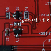
昨日までこのTFT、動かせないんじゃないかと思っていたが、動いた。何をやったかと言うと、裏面のJ1と言うジャンパをハンダでショートさせて正式に5V仕様に変更しただけ。
これを買った時の商品説明には5Vでも3.3Vでも動くと書いてあった。なので最初はロジックレベルコンバータで3.3Vで動かしてみたがダメだった。レベルダウンせずに5Vでもやってみたがそれもダメ。と言うのが昨日まで。
今朝再度ネット検索すると面白いサイトを見つけた。マニュアル集みたいな英語サイトで、いろいろ丁寧に説明が書いてあった。が、この5Vジャンパ以外別に間違った事はしていないのもわかった。なので半信半疑でハンダブリッジをやってみた。
LCDwiki
あっ、動いた!

ってわけ。これでダメなら実はコントローラがILI9341って買いてあったけれど実はデタラメじゃないかと疑おうとしていたのだった。
スケッチはこんな感じ。
前にも書いた通り、誰かがメンテナンスできるように初歩的な書き方しかしていない。
#include
#include
#include
// For the Adafruit shield, these are the default.
#define TFT_RST 8
#define TFT_DC 9
#define TFT_CS 10
#define sclk 13 //要らないかも。スタディしながら書いてたのが残ってた。
#define mosi 11 //これも不要。
//おまじない。↓
// Use hardware SPI (on Uno, #13, #12, #11) and the above for CS/DC
Adafruit_ILI9341 tft = Adafruit_ILI9341(TFT_CS, TFT_DC, TFT_RST);
//Analog pin numbers アナログピンの番号指定。
int If = 0; //Infeed
int G1 = 1; //1u G
int G2 = 2; //2u G
int C2 = 3; //2D Cooling
int G3 = 4; //3u G
int C3 = 5; //3D Cooling
// Gear ratio ギヤがあるのでギヤ比
const float gIf = 3.2; //Gear set spec 1:3.2
const float gG1 = 3.2; //Gear set spec 1:3.2
const float gG2 = 3.2; //Gear set spec 1:3.2
const float gC2 = 3.2; //Pulley 30:96 =1:3.2
const float gG3 = 3.2; //Gear set spec 1:3.2
const float gC3 = 3.2; //Pulley 30:96 =1:3.2
//スケッチ内で計算しなくて良いように定数をまとめた
// Constant for calculation
const float a = 226.08;
// Speed スピードの変数指定 単位はm/min
float sIf = 0;
float sG1 = 0;
float sG2 = 0;
float sC2 = 0;
float sG3 = 0;
float sC3 = 0;
void setup() {
// TFT おまじない
tft.begin();
tft.fillScreen(ILI9341_BLACK); //全面黒で塗り潰し
tft.setRotation(3); //Landscape screen //画面の向き指定
// for serial output (Comment out when running) デバッグ用
//Serial.begin(9600);
}
void loop() {
//後から見る人への解説
// 5V = 50Hz -> Voltage x 10 = Freq
// Pole = 4
// rpm(motor) = (120 x Freq)/p = 30 x Freq
// rpm(roll) = rpm(motor) / GearRatio
// Speed = rpm(roll) x π x diameter
// diameter = 0.24[m]
// Speed = (226.08 x Voltage) / GearRatio
// Voltage reading アナログ電圧読み込み
sIf = a * analogRead(If) / gIf;
sG1 = a * analogRead(G1) / gG1;
sG2 = a * analogRead(If) / gG2;
sC2 = a * analogRead(G1) / gC2;
sG3 = a * analogRead(If) / gG3;
sC3 = a * analogRead(G1) / gC3;
// Voltage reading debug onpy (comment out while run) デモ用
// Input voltage simulation
//sIf = a * 0.01 / gIf;
//sG1 = a * 1.00 / gG1;
//sG2 = a * 2.00 / gG2;
//sC2 = a * 3.00 / gC2;
//sG3 = a * 4.00 / gG3;
//sC3 = a * 5.00 / gC3;
//Debug only (comment out when run) デモ用
//sIf = a * 1 / gIf; //If=1V
//sG1 = a * 2 / gG1; //G1=2V
//sG2 = a * 3 / gG2; //G2=3V
//sC2 = a * 4 / gC2; //C2=4V
//sG3 = a * 5 / gG3; //G3=5V (Max voltage value)
//sC3 = a * 6 / gC3; //C3=6V (impossible)
//for debug only (Comment out when actual running) デバッグ用
//Serial.print ("Infeed :");
//Serial.println (sIf);
//Serial.print ("1u Groll :");
//Serial.println (sG1);
//Serial.print ("2u Groll :");
//Serial.println (sG2);
//Serial.print ("2D Cool :");
//Serial.println (sC2);
//Serial.print ("3u Groll :");
//Serial.println (sG3);
//Serial.print ("3D Cool :");
//Serial.println (sC3);
//for display TFT ここからTFT表示
//最初に画面上にタイトルを表示
tft.fillScreen(ILI9341_BLACK); //screen reset with black color
tft.setCursor(0, 0);
tft.setTextColor(ILI9341_RED); //text color (adjust)
tft.setTextSize(2); //text size (adjust)
tft.println ("Roll SPEED METER"); //Display title
tft.println (" ");
tft.setTextSize(3); //text size
//ここから下が各スピードの表示
tft.setTextColor(ILI9341_BLUE); //text color
tft.print ("(回転物1) :");
if (sIf > 500 || sIf < 0){ //値が変な時はエラー表示
tft.println ("ERR");
}else{
tft.println (sIf);
}
tft.setTextSize(1); //gap size
tft.println (" ");
tft.setTextColor(ILI9341_WHITE); //text color
tft.setTextSize(3); //text size
tft.print ("(回転物2) :");
if (sG1 > 500 || sG1 < 0){
tft.println ("ERR");
}else{
tft.println (sG1);
}
tft.setTextSize(1); //gap size
tft.println (" ");
tft.setTextColor(ILI9341_BLUE); //text color
tft.setTextSize(3); //text size
tft.print ("(回転物3) :");
if (sG2 > 500 || sG2 < 0){
tft.println ("ERR");
}else{
tft.println (sG2);
}
tft.setTextSize(1); //gap size
tft.println (" ");
tft.setTextSize(3); //text size
tft.print ("(回転物4) :");
if (sC2 > 500 || sC2 < 0){
tft.println ("ERR");
}else{
tft.println (sC2);
}
tft.setTextSize(1); //gap size
tft.println (" ");
tft.setTextColor(ILI9341_WHITE); //text color
tft.setTextSize(3); //text size
tft.print ("(回転物5) :");
if (sG3 > 500 || sG3 < 0){
tft.println ("ERR");
}else{
tft.println (sG3);
}
tft.setTextSize(1); //gap size
tft.println (" ");
tft.setTextSize(3); //text size
tft.print ("(回転物6) :");
if (sC3 > 500 || sC3 < 0){
tft.println ("ERR");
}else{
tft.println (sC3);
}
delay (200); //checking interval 100=0.1sec
}
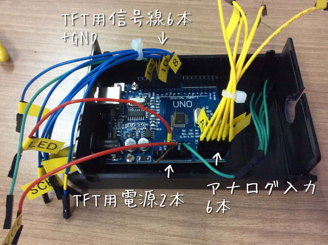
前提条件として、これはYokogawaのインバータの多機能アナログ出力をアナログ入力する事を想定。出力のタイプは回転数 (回転数をDC電圧に読み替えて出力している)。アナログ最大出力はデフォルトで10Vなのでゲインを50%に設定して最大出力が5Vになるようにする。


修正 2019/04/10
上記のスケッチに間違いがあるので下記のように修正します。
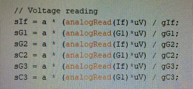
変数uVの追加

アナログ読込値を電圧に変換する。

アナログ値が直に電圧の値になっていると思い込んでスケッチを書いてしまったが、そんなわけはないので電圧値に変換するように式を変更した。


