PIC12F1840を使って、MCCを利用したADCテストをやってみました。
PICを変更したのは、PIC12F1822では、メモリが足りなくなりそうだからです。
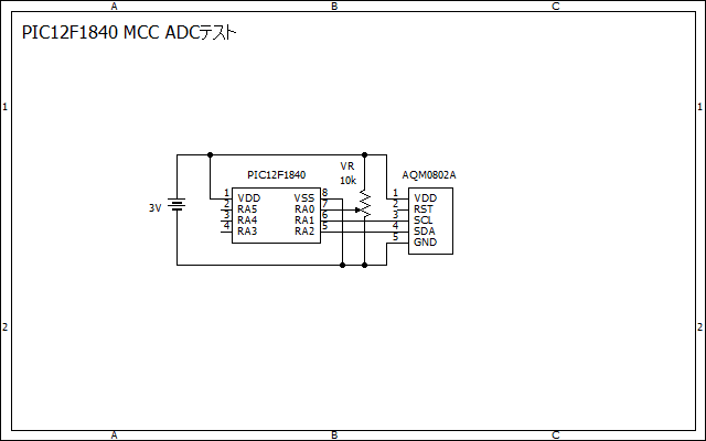
アナログ入力ポートはRA0(AN0)とし、RA1,RA2をI2C通信に利用します。
AN0の電圧を10kΩのボリュームで調整して、電圧の値をAQM0802Aに表示します。

プロジェクトを作成して、MCCを開きます。
System Moduleの設定は、INTOSC,FOSC,16MHzとしました。
I2Cの設定とプログラムは、前の記事と同じです。
今回は、ADC関係の設定だけ紹介します。
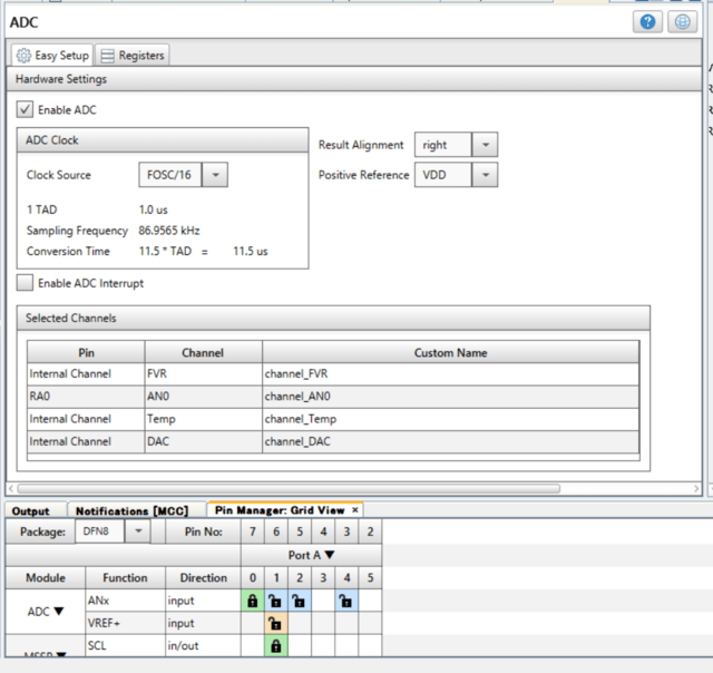
Enable ADCにチェックを入れ、ADCを有効にします。
ADC Clockは、F1シリーズでは、1us~9usの範囲で設定しますので、変換クロック(Tad)は、FOSC/16 = 1.0usとしました。従って、Conversion Timeは11.5usとなります。
変換結果の格納方式(Result Alignment)は、右詰め(right)
正参照電圧(Positive Reference)は、電源電圧(VDD)としました。

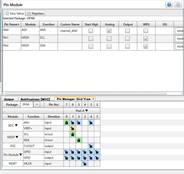
Pin ManagerとPin Moduleに自動的にADCが設定されます。
RA0にアナログポートAN0が設定されました。

設定は、これだけです。
プログラムは次のとおりです。
ADCに関係するのは、main()の中のprintf()関数の中の
ADC_GetConversion(0)
だけです。なんだか拍子抜けするくらい簡単です。
---------------------------------------------------------
/*
* PIC12F1840 MCC ADC test
* 2021.05.18
* JH7UBC Keiji Hata
*/
#include "mcc_generated_files/mcc.h"
#include "mcc_generated_files/examples/i2c_master_example.h"
#define I2CLCD_AQM0802A 0x3e
//-------- send character ------------------------
void LCD_dat(char chr)
{
I2C_Write1ByteRegister(I2CLCD_AQM0802A, 0x40, chr);
__delay_us(30); // 30us
}
//-------- send command -------------------------
void LCD_cmd(char cmd)
{
I2C_Write1ByteRegister(I2CLCD_AQM0802A, 0x00, cmd);
if(cmd & 0xFC) // bit6 = 1
__delay_us(30); // 30us
else
__delay_ms(2); // 2ms Clear or Home
}
//-------- clear LCD--------------------------
void LCD_clr(void){
LCD_cmd(0x01);
}
//--------- Home -----------------------------
void LCD_home(void){
LCD_cmd(0x02);
}
//--------- Cursor X,Y -----------------------
void LCD_cursor(unsigned char x,unsigned char y){
if (y == 0)
LCD_cmd(0x80 + x);
if (y == 1)
LCD_cmd(0xc0 + x);
}
//-------- display strings -------------------------
void LCD_str(char *str){
while(*str)
LCD_dat(*str++); //pointer increment
}
//-------- write 1 character to LCD ----------------
void putch(unsigned char ch){
LCD_dat(ch);
}
//-------- LCD initialize ---------------------------
void LCD_init(){
__delay_ms(40); //40ms wait
LCD_cmd(0x38); //8bit,2line
LCD_cmd(0x39); //IS=1 : extention mode set
LCD_cmd(0x14); //Internal OSC Frequency
LCD_cmd(0x70); //Contrast set
LCD_cmd(0x56); //Power/ICON/Contrast Control
LCD_cmd(0x6C); //Follower control
__delay_ms(200);//200ms wait
LCD_cmd(0x38); //IS=0 : extention mode cancel
LCD_cmd(0x0C); //Display ON
LCD_cmd(0x01); //Clear Display
__delay_ms(2); //wait more than 1.08ms
}
void main()
{
// initialize the device
SYSTEM_Initialize();
// Enable the Global Interrupts
INTERRUPT_GlobalInterruptEnable();
// Enable the Peripheral Interrupts
INTERRUPT_PeripheralInterruptEnable();
//I2C_Initialize();
LCD_init();
char msg[] = "ADC TEST";
LCD_str(msg);
while (1)
{
LCD_cursor(2,1);
printf("%4d",ADC_GetConversion(0));
__delay_ms(100);
}
}
---------------------------------------------------------
{
// initialize the device
SYSTEM_Initialize();
// Enable the Global Interrupts
INTERRUPT_GlobalInterruptEnable();
// Enable the Peripheral Interrupts
INTERRUPT_PeripheralInterruptEnable();
//I2C_Initialize();
LCD_init();
char msg[] = "ADC TEST";
LCD_str(msg);
while (1)
{
LCD_cursor(2,1);
printf("%4d",ADC_GetConversion(0));
__delay_ms(100);
}
}
---------------------------------------------------------
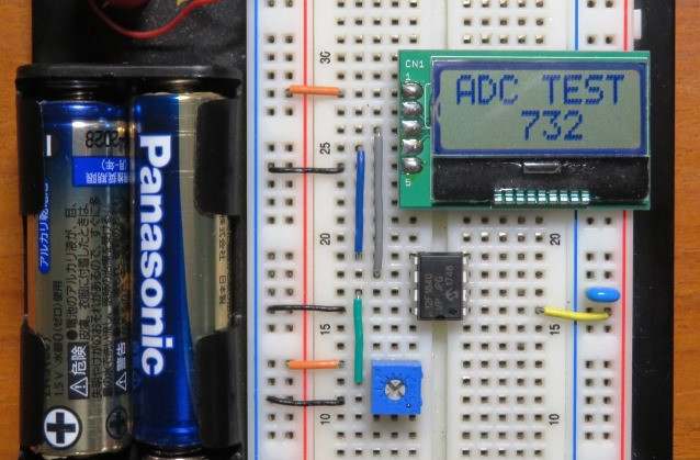
ブレッドボードです。
VRの位置により、0~3Vの電圧が、0~1023の値で2行目に表示されました。


