Exchange the coupler of Class 91 into close coupler.
Before modification, comparison of Class 91 and DVT. The height of buffer is different, and the gap between the front skirt and the body of Class 91 is too wide.
The coupler height of Class 91 and modified Mk4 coach is also different.
So I decided to attach the buffer/skirt part of Class 91 onto the body side.
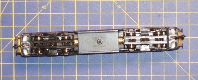
Before Modification. Bogie frame can be detached from inside gear frame by pulling downward.
(It's better to remove the Chinese oil before modification, for your health.)
Replace the Arnold coupler with Tomix latch type TN coupler (no. 0381) which is compatible with the close coupler of modified Mk4 coaches.
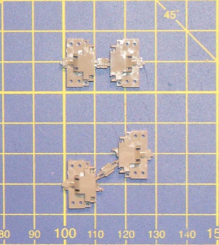
Cut out the skirt/buffer part from bogie frame, and replace the coupler.
Bottom view of the body. Measure the inner width of the body. Front end is tapered and the shorter span at frontmost position shall be measured, too.
Cut out 5mm width pieces from 1mm thick plasticard, trim the length into the inner width of the body (front end one shall be tapered), and glue onto upper surface of the skirt/coupler parts.
Glue the skirt/buffer parts onto bottom edge of the body, and install the power unit.
Comparison of coupler height. Same as Mk4 coach.
After modification.
I'll replace the pantograph with Fleischmann or Minitrix part, because the collector head cannot be horizontal....
Working head/tali lights are another issue.
GNER was one of my favorite TOCs, but he had gone.
So I bought a set of Farish IC225 consists of Class 91 EL, 8 Mk4 PCs and a DVT to record the GNER livery in my model collection.
The design of Farish N scale models is quite different from that of Japanese and continental products, and it's difficult for me to accep the models just out of box.
So I will try to upgrade the IC225 step by step before putting into service.
First step ? replace the coupler into Japanese close couplers.
Before modification - too wide gap between vehicles.
Japanese products. Body mount close couplers, No. 0335 by Tomix. (Black version, No. 0331, is also available.)
Extended condition.
Remove the flanges on upper side and trim the width of the base into 15mm.
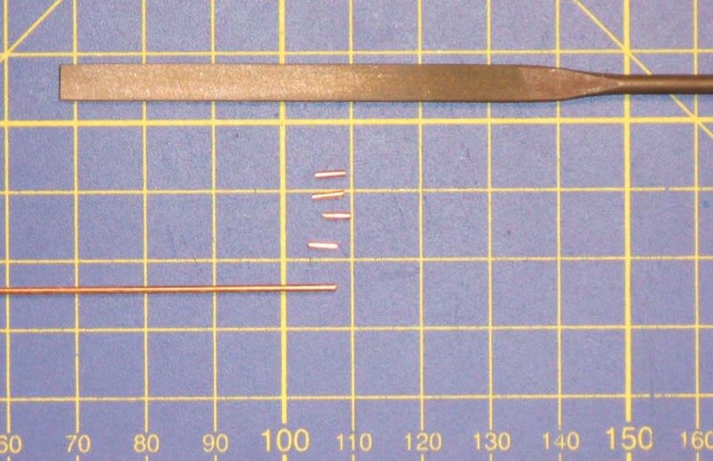
Making guide pins. Cut 1mm dia brass wire into approx 3mm length, and file the burr.
Drill the holes for the guide pins on the skirt part of a bogie. Mark the centre position, 2.0mm from both sides and 3.0mm from the end beam. (I always use the depth gauge of a vernier caliper to mark the position.) Then drill the 0.5mm dia guide holes.
Enlarge the guide holes to 1.0mm dia.
Cut the coupler part from the bogie.
Cut the side skirt parts obliquely.
Insert the guide pins into the holes of the coupler part.
Attach the side skirts onto the coupler parts by using the guide pins. Don't glue them at this moment.
Put the coupler parts with side skirt onto the chassis, adjust the side skirts in parallel with the body side, and fix them by adhesive.
After modification. Very cool, isn't it?
Next step is the modification of a locomotive. To be continued.


