


I modified another driving car, and tested on the curved track.

On R650 curve. Passed.
On R650 reverse curve. Passed.
I modified another driving car, and tested on the curved track.
On R650 curve. Passed.
On R650 reverse curve. Passed.
I bought 2 sets of Hornby Class 800 5-car trains to enjoy 2-unit coupled operation.
At first, disassemble car 5 (Driving Standard car).


Dummy front coupler is installed onto the NEM pocket, but cannot be used for the operation. I tried to install close coupling device.
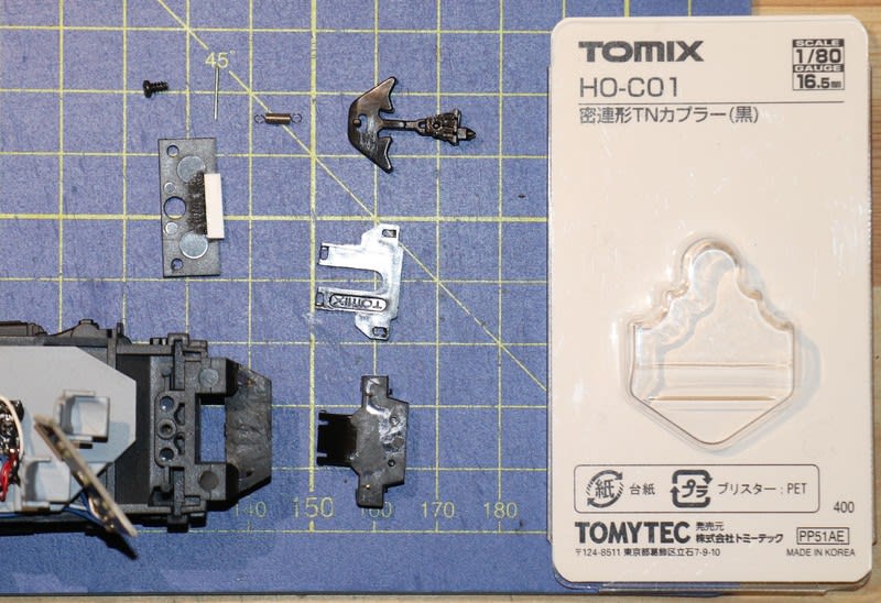
Same as the case of Hornby Class 395, I prepared TN close coupling by Tomytec. Remove the NEM pocket, and trim the front end of chassis carefully to make the installation space.
Trim the casing of coupling unit smaller, but not to lose the function.

First trial was like this, but failed. The coupler head was too long to fit the coupler hatch.

So I trimmed the coupler casing much smaller. The fixing clips at the rear must be removed, so a pair of brass pins were fitted to fix the upper lid.
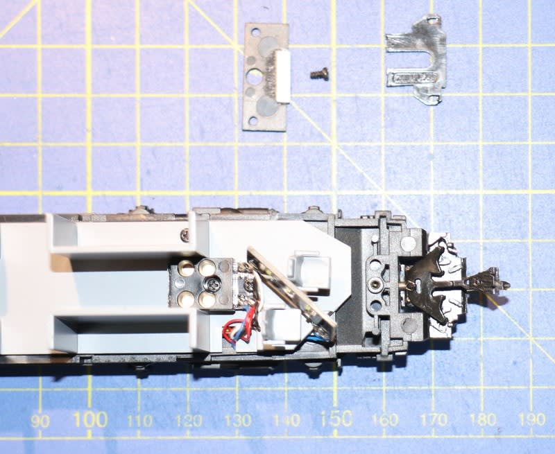
The casing was fixed onto the chassis by the other brass pins.
A 1.8mm dia hole was drilled on the bulkhead of the chassis to store the centring spring. The rear end of the spring was fixed by a short brass pin in the screw hole.
The spacer of the head light unit holds the coupling unit. A small piece of stylene was glued onto the spacer to fill the gap.
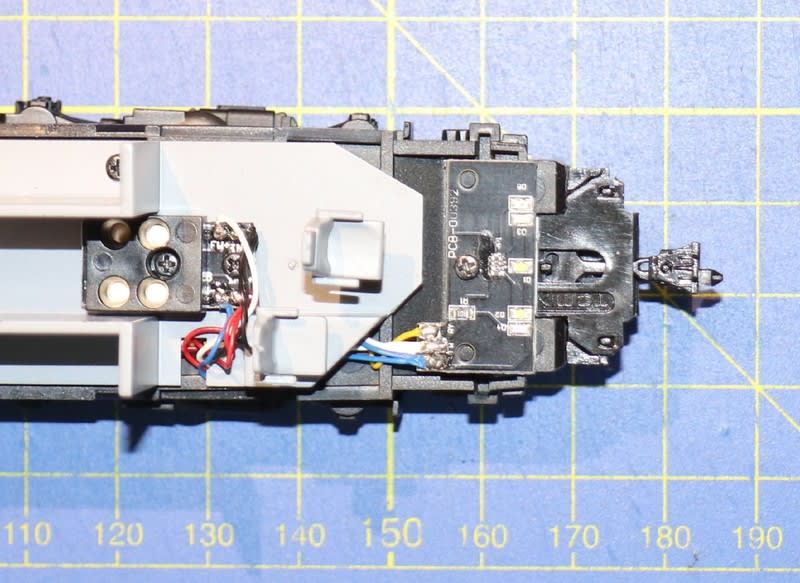
Fit the upper lid, and install the head light unit.


After assembly. The coupler is swinging smoothly, but the coupler head still disturbs installing coupler hatch.

The motor car (car 1, Driving First) has the die-casted metal chassis, and it's hard to modify. So another coupling unit will be instlled onto car 5 of another train.
The orignal pantographs have functional and cosmetic issues. The biggest issue is the collector head that cannot be kept its horizontal position. DC kits supplies the replacement parts for EM1/EM2.
製品に付いていたパンタの見栄えが??で、動きも渋く、舟体がすぐに傾いてしまうため、ガレージメーカの交換用パンタをネットで探して購入。Pacerは、このパンタのついでにポチった。


The original pantographs are glued onto the roof tightly together with the insulator bases. Detach the original parts carefully by digging the glue from inside using a pin vice and a drill bit. Cut the insulators at the bottom using a saw and reuse the insulator bases.
元のパンタは碍子、パンタ台共々、屋根にしっかり接着されており、屋根裏から取付足をドリルで掘って接着剤を削り、何とか取り外した。パンタ台は再利用することにし、碍子を切り離した。

Drill the 2mm dia installation holes of the new pantographs at the centre position of the 4 holes for the original insulator bases. It's better to locate the centre position by using the template.
交換用パンタは中心でネジ止めなので、テンプレートで四隅の碍子取付穴の中心に穴あけ。テンプレートに裸電球が写り込んでしまったが気にしないでください。
The pitch of the insulators of new pantograph is a little smalle than that of original one, and the insulators of new pantograph don't sit on the insulator bases. So the insulator bases must be expanded by gluing small pieces of stylene rods.
パンタ台のピッチと新パンタの足ピッチが合わないため、パンタ台をプラ材で拡張。


File the top surface of the base, and paint in similar colour.
上面を平らに仕上げて、類似色のHambrolエナメルで塗装。英国ではまだHambrolを普通に売っている。

Install new pantographs by screws. Fixed it!
交換用パンタをネジ止めして、完成。

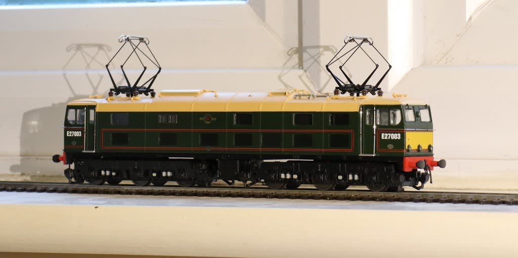
The exchange works were complicated, but I'm happy with the results.
London Tube 1959 stock (Piccadilly Line) die-cast display models by Exclusive First Editions. I bought them at London Transport Museum shop.
This model is for display purpose, but the bogies and wheelsets can be rotated. So I tried to motorize them.

(Click pictures to enlarge.)
The design concept is to minimize the modification onto the original model, and to keep the drive mechanism as low as possible.
I selected the "LoBoy" gear drive by Hollywood Foundry.au, and 14mm dia DC motor. Cut out the interferred part of the chassis and interior molding, as shown in the photos. The motor can be installed just below the seat back.

Close-up of the motor and body bolster made from polystilene sheet.

Close-up of the gear drive. The inner part of original bogie was removed and the bogie frame was glued onto the gear frame.

The completed 3-car trainset. The drive mechanism cannot be seen from the side window.

The inter-car drawbar provided is difficult to connect & disconnect. I'll replace it with the coupling device with bus line connection to improve the current collection, and for the future provision of interior lighting.
To be continued....?
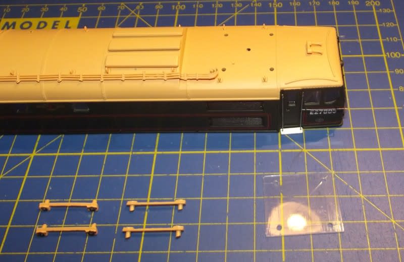
Made from resin casting kit and related parts by DC Kits.
Yellow/black stripes and car number lettering have not yet applied.
Front end parts were modified to the original wide windscreen.
Motorized by 2 sets of Tenshodo motor bogies fitted on the motor car.


Driving Trailer Second car

Motor Second Car

It seems better to lower the body height a little.
I bought 2 x 6-car units of Hornby Class 395 train models to enjoy 2 units coupled train.
At first, I removed a front coupler hatch by releasing the snap-on hooks at both sides of the hatch, and push them toward front. Then I found a 2x3mm rectangular hole that is suitable for the NEM swallow tail coupler.

Of course, I tried loop couplers. But...

The coupler overthrow on R600 reverse curve is like this. This option cannot be used.

HO scale close coupling made by Tomix.jp.

Disassemble like this by releasing snap-on latches. Trim the tabs at both sides of coupler case, not to damage the guide groove.

I didn't use the top cover plate to install the coupler at higher position. Made holes and a groove on the chassis same as the top cover plate by using it as a template.

Enlarge the coupler hole to the same size as that of coupler case.

Fit the assembled coupler onto the chassis. I tried to glue the coupler box but the glue didn't work. therefore I made a fixing plate from thin brass sheet and screwed it onto the chassis.

Fixing plates, before & after.

After installation. You can find white plastic pieces at both sides of the coupler opening. These pieces shall be fitted to support the chassis at its position.

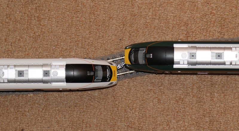
Coupled condition. Looks like real train!

On R600 reverse curve, still kept coupled!
Of course, I did running tests. This coupling system worked well.

When removing the coupler hatch, I broke some of the guide pins on the top and bottom of the hatch. I glued the new pins on the hatch and reopen the guide holes. The hatch is supported by these guide pins only, because the snap-on hooks were broken, too.


