


US2019380316(*既出)
[0108] FIG. 9A
【図9A】図9Aは、
shows results in connection with an embodiment of the invention,
graphing the percentages (y-axes) of all functional immunoglobulin (Ig) reads resulting from a DH -DH recombination event (bottom panel) that have a CDR3 of a particular amino acid length (x-axes) isolated from animals modified with the 12:DH 2-2:23|12:DH 2-8:23|12:DH 2-15:23 targeting vector.
12:DH2-2:23|12:DH2-8:23|12:DH2-15:23ターゲティングベクターで修飾された動物から単離された特定のアミノ酸長(x軸)のCDR3を有するDH-DH組み換え現象(下部パネル)から生じる、全ての機能的免疫グロブリン(Ig)読み取りのパーセンテージ(y軸)をグラフ化する、
本発明の実施形態に関連する結果を示す。

US8574346(*既出)
[0124] The appended FIG. 1 shows the results obtained with, on the x-axis, the ratio of the diameters of the particles (equivalent diameter of the particles of the lower layer/diameter of that of the particles of the upper layer)
【0087】
添付した図1は、x軸では、粒子の直径の比(低い層の粒子の等価直径/上層の粒子のものの直径)を、
and, on the y-axis, the ratio of the tamped densities of the two beds (density of the upper bed/density of the lower bed).
y軸では、2つのビーズの重装かさ密度(上部の床の密度/下部の床の密度)により得られた結果を示す。

US10163695(*既出)
[0067] FIGS. 6B-D are graphs showing the results of XPS analysis for specific orbital peaks of the various elements.
【0067】
図6B~図6Dは、様々な元素の特定の軌道ピークのXPS分析の結果を示すグラフである。


EP3363461(*既出)
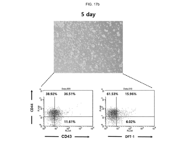
[0253] The obtained result was shown in FIG. 18a (result at culturing) and 18b (result after culturing for 5 days).
【0259】
前記得られた結果を図18A(培養時の結果)および18B(5日間培養後の結果)に示した(*図はそれぞれ恐らく17a, 17bの誤記)。
The top of each figure was the microscopic image and the bottom was the graph showing the result of flow cytometry.
各図の上段は顕微鏡の撮影イメージであり、下段は流細胞分析の結果を示すグラフである。


US2020096672(*既出)
[0092] FIGS. 37A and 37B show results of imaging the USAF resolution target using the metalens triplet.
【0045】
図37(a)及び図37(b)は、メタレンズトリプレットを使用した、USAF分解能ターゲットの撮像結果を示す。

WO2015105573(*既出)
Such a termination structure can extend the boundary of the electric field profiles while additional trench cells can further reduce the impact on the electric field distribution which arises from variations in the length of the field plate.
かかる終端構造は、電界プロファイルの境界を延長することができると同時に、追加のトレンチセルは、フィールドプレートの長さの変化から生じる、電界分布への影響を更に低減することができる。
Simulation results will be presented showing the influence of the termination structure on the breakdown voltage.
耐圧に及ぼす終端構造の影響を表すシミュレーション結果を示す。
WO2014076653(*既出)
Table 1 below summarizes the point angle-helix angle combinations tested to determine optimum helix angle, per the graph of Fig. 3 showing the results.
下表1は、結果を示す図3のグラフによる、最適なねじれ角を決定するために試験された先端角-ねじれ角の組み合せをまとめている。

WO2012085710(*既出)
More particularly, Table 2 provides the results for the balloons of the inventive inflatable retention system of the present invention (e.g., polyurethane balloons) in comparison to conventional silicone balloons.
より具体的には、表2は、本発明の膨張式固定システムのバルーン(例えば、ポリウレタンバルーン)を従来のシリコーンバルーンと比較した結果を示す。

US2017242010(*既出)
Eventually, these HCV Ags/Abs complexes will react with the preloaded HCV-specific capture monoclonal or polyclonal antibodies, and be immobilized at the test line area to form a colored band that indicates a positive test result (FIG. 2 “F”).
最終的に、こうしたHCV Ags/Abs複合体は、あらかじめ装填されたHCV特異的捕獲モノクローナルまたはポリクローナル抗体と反応し、試験ライン領域に固定化されて、陽性の試験結果を示す呈色したバンドを形成する(図2「F」)。
US10325861
In some cases, FIG. 3B shows a result of patterning of the KE resist layer 310 with first part 310 a having an inner sidewalls 320 a forming one wall of opening 320. Layer 310 also has second part 310 b having an inner sidewalls 320 b forming an opposite wall of opening 320. Sidewalls 320 a may extend vertically straight above and extend along pattern 134 (including in region 132 a) with the corresponding sidewalls 150 a of stack 150. Sidewalls 320 b may extend vertically straight above and extend along pattern 134 (including in region 132 a) with the corresponding sidewalls 150 b of stack 150.

US9043322
FIG. 13 shows an example result set 1302 and an example label histogram 1304. Example result set 1302 contains N results. Of the N results, a result 1320 is shown at position 1, a result 1330 is shown at position 2, and a result 1340 is shown at position 3. Result set 1302 is shown as a table where each row shows a result and each column shows an element of the result. Column 1306 shows a position. Column 1308 shows a title. Column 1310 shows a snippet. Column 1312 shows a URL. Column 1314 shows one or more labels.

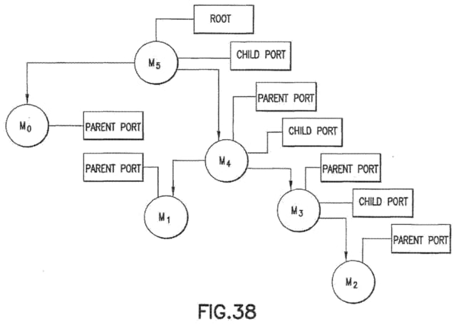
US20200166913
FIG. 38 shows a result of a typical IEEE 1394b self-identification process. It is important to note that other network implementations may also be capable of such self-identification and that the disclosed embodiments are not limited to IEEE 1394b type networks.
US11338923
FIG. 14 shows a first design for a rotor protection shroud (RPS), consistent with various embodiments.
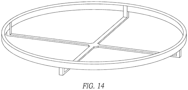
FIG. 15A shows a result of the stress analysis of the RPS designed based on the first design of FIG. 14, consistent with various embodiments.


