


WO2014078626
[0059] Example arrangements in which a maximum pore space is determined are illustrated in FIGS. 12A-12B.
【0059】
最大孔隙空間が決定される例示的な配置構成を、図12A~12Bに示す。
In particular, FIGS. 12A-12B illustrate that, within the volume 1000, example pore size spheres 1202, 1222 are illustrated to shown pore sizes that are possible for formation of clathrates.
特に図12A~12Bは、体積1000内で、例示的な孔径球体1202、1222がクラスレートの形成を可能にする孔径を示すように例示された状態を示す。
The radius of the inscribed sphere is the pore size, and a maximum pore size determined in this manner is an estimated maximum pore size expected to be observed in the sample under consideration.
内接球体の半径が孔径であり、この手法で決定された最大孔径は、検討中のサンプルで観察されることが予測される推定最大孔径である。
FIG. 12A illustrates modeling of pore size spheres 1202 inscribed between adjacent grains 1102 of FIG. 1 1A, which were in point contact with each other.
図12Aは、互いに点接触した図11Aの隣接粒子1102間で内接する孔径球体1202のモデリングを示す。
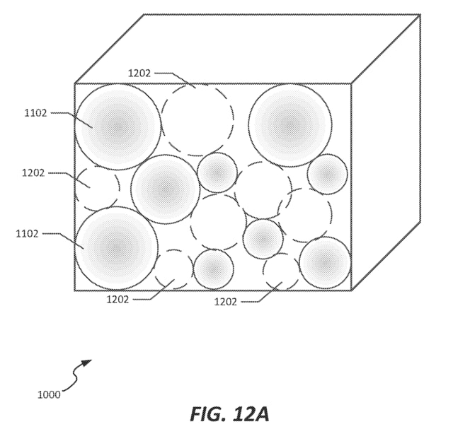
FIG. 12B illustrates modeling of pore size spheres 1222 inscribed between grains spaced apart by one or more proscribed distances, e.g., distances 1124, 1 126 of FIG. 1 1B.
図12Bは、1つ又は複数の所定距離、例えば図11Bの1124、1126の距離だけ間隔を空けて配置された、細粒間に内接する孔径球体1222のモデリングを示す。


※コメント投稿者のブログIDはブログ作成者のみに通知されます