遅ればせながら2ヶ月遅れでCQ誌1月号を入手しパラパラとめくっていたら新しいコラムであるHigh Band DXingでFT4TAのDXペディションで使用されたVDA(Vertical Dipole Array)についての紹介されていました
個人的には2013年にV25AでCQWWCWに参加する際にこのアンテナを検討したのですが情報が少なかったことから準備が間に合わず、ここ最近は軽量化のためハイバンドはSteppIRのSmallIRを利用してお蔵入りの状態です。
しかしながらやはり無指向性のシングルエレメントでは色々と限界もあり指向性のあるアンテナを使いたいというのが本音です。
時を同じくしてオランダのDKARからいつからかEメールで送られるようになったDKARマガジンをみていたらVDAについての記事がありました。
このマガジンはオランダ語と英語の記事がありますがたまたまこの記事については英語でしたのでご参考に抄訳を載せておきます。

バーチカルダイポールアレー(VDA)アンテナ
By By Remco den Besten PA3FYM / 7QNL
短波におけるDXペディション用の高ゲインかつ軽量のアンテナへの需要は探求は今もなお続いている。無償で提供されるアンテナモデリングソフトウェアのおかげでバーチカルダイポールアレー(VDA)におけるいくつかの進展をより明示的な例として示すことが可能になったことに感謝しないといけない。
私自身が調べた範囲ではVDAがDX(ペディション)の世界に紹介されたのは2008年のDucie島からのVP6DXによるDXペディションからである。その後、その他のDXペディションでもVDAは成功裏に利用されてきている。
本稿ではVDAの詳細について述べるとともに島、キャンプサイトまたは山の頂上においてまた場合によっては自分の庭においてこのアンテナをどのように製作するかについての解説を試みたものである。
モクソン効果
VDAではモクソン効果を考慮しないといけない。モクソン効果は、1993年にG6XN Moxon が発表したもので、2エレ八木の放射器と反射器の間の容量結合によるものである。容量結合が発生するのは放射器と反射器の先端がそれぞれに向かって90度曲げられた場合である。通常の2エレと比較すると、実際にはモクソンアンテナは全般により小さく寸法で同等の放射パターンを得ることができる。適切に設計された場合にとても利用価値のある副産物はマッチングが50オームであることである。言い換えると、賢く曲げることによる寸法、放射パターン(ゲイン)およびインピーダンスでメリットを得ることができるのである。図1はモクソンアンテナの基本的な構造を示している。
図1

バーチカルダイポールアレー(VDA)
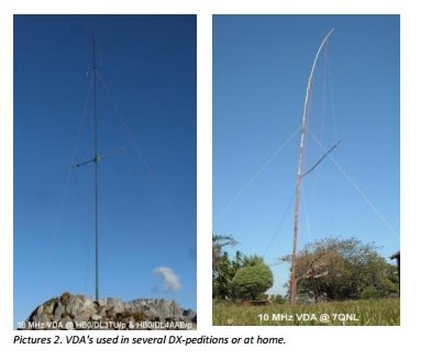
アンテナの名前からわかるとおりダイポールアンテナを配列したものである。理由はともあれここ数年の間にVDAという略称はダイアモンドの形状をした2エレメントの垂直八木を意味するように変わってきた。もちろんモクソンアンテナを垂直にすることもできるが、VDAと比べるとより構造的な困難を伴う。この点については後でより詳細に検討する。写真2はVDAの例である。
写真2
VDAの放射パターン
垂直アンテナのよい特徴は打ち上げ角が低くDXに向いていることである。VDAも低い打ち上げ角となるが、設置する場所のグランドによる。この点については後で述べる。図3は24MのVDAの3次元放射パターンで、図4は打ち上げ角18度での断面である。
図3

図4
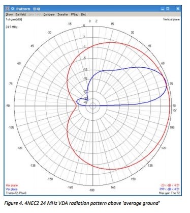
明確に見て取れるのは放射パターンにおいて深いくぼみがあることで、これは反射器によるものである。このくぼみは望まない方向からの混信を抑制するのにとても便利である。実際にはこのくぼみはシャック内でのインターフェアなどを抑制するのにもとても役立つ。メインローブの形状は正規のもので、垂直面にはくぼみはないことは注目すべき点である。この点についてスパイダービームやHexビームといった水平(八木)アンテナにおいてはそのようにはならない。自由空間においてこれらのアンテナはよい放射パターンを示す。しかしながら、実空間においてこれらのアンテナを設置した場合、例えば1/2波長の高さで深いくぼみが発生し、特定の打ち上げ角での減衰をもたらす。これにより適切な方向にビームを向けているにもかかわらず聞こえないということが発生する。普通のグランドに設置したVDAのゲインは約4-5dBiである。
VDAの性能
おとぎ話流の言い方をするならば、「海水の近くにアンテナを設置する予定がないのであれば、このアンテナのことは忘れてその他のアンテナデザインを探したほうがよい。VDAが性能を発揮するのは、唯一、海水の近くであり、目的のDXの方向に向けて海がある場合である」
オランダでは、この種のおとぎ話は理にかなっていないと考えられている。もちろん、ビバレッジやそれに似たアンテナは除いて、全てのHFアンテナは良好なグランドまたは海水上でよりよい性能を発揮する
VDAが海水以外のグランド上で性能を発揮しないと言うことは、「ルノーを高速道路で運転することを考えていないのであれば、ルノーは忘れて他のメーカーの車を探しなさい。ルノーは高速道路でだけで、パリに向かって運転するときののみ性能を発揮するのだから」といっているのと同じだからである。
図5はVDAが平均的なグランド(赤)と海水(青)に設置された場合の垂直面の違いを示している。
図5

(もちろん)海水上のアンテナの性能がより良いことは明確に見て取れる。メインローブは約5dB強く、打ち上げ角は「平均的なグランド」上に設置されたVDAのものよりも約半分である。しかしながら、その単純さと予測される放射パターンを考慮すると、個人的な意見としてはVDAは全ての種類のグランドにおいても「費用に一番見合った」アンテナと言えると思う。
VDAの寸法
VDAの全体の寸法はダイアモンドのサイズ、すなわちアンテナ全体の高さおよび反射器エレメントと放射器エレメントの間の距離によります。しかしながら、VDA効果を得るための一定の境界寸法はあります。このアンテナは望ましい放射パターンおよび50+j0Ωでのマッチングを持っていなければなりません。これらの基準に近づけるためのいくつかの方法があります。
モデリングによる実験によりこのアンテナの全体の高さと放射パターンの間でのほどよい妥協点を得ることができました。
図6はの短め(7m)とちょっと長め(8m)の24MHzのVDAで放射器と反射器の間の距離は同じのときの違いを示しています。
図6
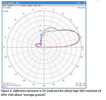
高さが長めの方では打ち上げ角が幾分低く、ゲインも少し多めです。図6の例での打ち上げ角の計算値は7m長と8m長で18度と16度となります。いくつかのモデリングを行ったあと、図7に示すような汎用的なVDAの寸法を導き出しました。全体の高さは1/2波長より少し長めですので、垂直代ポールを作りたいのであれば、代わりにVDAを考えてみてください。
図7

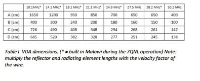
反射器エレメントと放射器エレメントの長さには使用するワイヤーの短縮率(velocity factor (vf) )をかける必要があります。実務的には直径2mmの撚り線ワイヤーの短縮率は0.96です。混じりのない鉄製またはアルミニウムの直径2mmのワイヤの短縮率は0.99です。表1には実際に製作したVDAの寸法を示しておきました。これらのアンテナは個々に最適化を施して、該当バンド内でのSWRが良好になるようになっています。その後、図7に示した一般的なVDAの寸法を私なりに導出しています。
表1
VDAの製作
VDAの製作は非常に簡潔です。必要なのはワイヤーと非電導性の幾分固めの一定の長さのポール、例えばグラスファイバー製の釣竿(カーボン製は駄目!)や(乾燥した!!)竹の他、枯れた松の木などです。
写真8
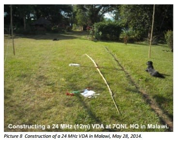
水平の棒は同じ材質のもので問題ありません。モクソンと相反したVDAのエレガントさは、その構造が三角形であることによる機械的な構造に内在する堅牢さにあります。反射器エレメントと放射器エレメントは(ナイロン)ロープで引っ張る必要があります。ロープの長さはピタゴラスの定理を使って計算することができます。
写真9

アンテナを立ち上げるためには地面に50-70cmの深さの穴を開け、穴の長さ分ポールの長さを追加します。15m用VDAの場合ポールの長さは最低9m必要です。
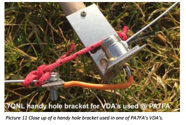
給電部分については、私は家で'7QNL handy hole brackets'を設計・製作しました。
このブラケットはいくつかの目的があります。
1) ブームに給電部分を固定すること
2) コネクタを収納すること
3) 下側のエレメントを接続すること
4) 上側のエレメントのための拘留施設(一本のロープ)として機能すること
写真10は20m用VDAに取り付けた7QNL handy hole bracketです。写真11は15m用VDA用のクローズアップです。
写真10

写真11
多分、絶対に必要ではないですが、あると良いと思われるのは給電線用のコモンモードチョークです。私自身は同軸に挟むフェライトクランプを使うのが好きです。経験からコモンモードチョークのリアクタンスは接続するインピーダンスの約10倍となります。ここでは10x50 = 500Ωとなります。私が使用しているクランプのインダクタンスは2 μHです。これらのクランプ2つで10, 12 および15mでは十分です。20mにおいては3つ、30mでは4つで十分です。写真12は7QNLにおける30m VDAの給電部分ですが同軸は40m用デルタループを流用したのでクランプが5つとなっています。
写真12

同軸を接続した後、同軸をブームに沿って反射器側に這わせます。タイラップで固定して同軸が地面に向かって傾斜させるようにします。こうすることによって同軸が放射パターンのくぼみ部分に位置することでアンテナに影響しないようにすることができます。プラスの副産物効果として同軸が必要に応じて支え綱としても機能することにもなります。写真2の7QNLとPA7FAにおける設置状況を参照のこと。同軸に関してはH155やAirce117といった最新のケーブルを使うようにしてください。私は軽量でやわらかく短波においてDXをするのに必要なパワーを扱うことができるのでH155が好きです。
調整
VDAが完成して設置後にマッチングがどうか測定して見てほしい。VDAは50+j0Ωでマッチングするように設計されているので普通のSWRメータで十分である。目標周波数でSWRが1.0になればそれで終わりである。私自身のほとんどすべての場合、目標周波数よりも少し低すぎるところ(例えば、目標周波数が21.1Mhzに対して20.9Mhz)でSWRが1となった。このような場合は、反射器エレメントと放射器エレメントの下側部分を数センチ短くして、再度マッチング測定し、目標周波数でSWRが1になるまでこれを続ける。何かの理由でアンテナが高い周波数でマッチングしている場合は、逆に下側のエレメントを長くする。
実際のVDA
その単純さからVDAは(DX向けの)びっくりするぐらいよいアンテナである。アフリカのマラウイで私は放射パターンのくぼみよるマイナス面の効果を経験することはなかった。図13はマラウイからの方位地図にVDAの計算した放射パターンを付け加えたものである。
図13

ショートパスにおけるノッチ部分にある局は後でロングパスによって簡単にQSOすることができた。オランダでは、VDAを300度の方向に向けると非常に効果的なコンテスト用アンテナであることを経験している。オセアニアが放射パターンのくぼみに位置するが、ここはロングパス経由で適度の強さで簡単に交信することができる。
まとめ
その単純さにもかかわらず、VDAはどのような種類の地面上においてもとても効率的なアンテナであることが証明されている。
VDAは簡単に製作でき、その構造は堅固である。また、VDAは直接50+j0Ωで給電可能である。正直なところ、あなた自身のためにこのアンテナを作ってみない理由が見当たらない。ぜひ試してみてほしい!
73 de Remco, PA3FYM
Email: pa3fym@dkars.nl
Vertical Dipole Array (VDA) antennas
By Remco den Besten PA3FYM / 7QNL
The demand for high gain and light weight antennas for DX-peditions on short wave is an on-going quest. Thanks to (free) antenna modelling software some progress is made of which the vertical dipole array (VDA) is a very illustrative example. As far as I could ascertain the VDA was introduced into the DX(-pedition) community in 2008 during the Ducie Island VP6DX expedition. Subsequently VDA's have been used successfully in other DX-peditions. This article attempts to elaborate on VDA's, how to build one on an island, a camping site, on top of a mountain or... in your garden.
Moxon effect
VDA's contain the 'Moxon effect'. This effect, published by Les Moxon G6XN in 1993, involves capacitative coupling between the radiator and reflector of a 2 el. Yagi. Capacitive coupling is realized by bending the reflector and radiator ends towards each other with a 90°angle. Compared to an ordinary 2 el. Yagi, in practice Moxon antennas have overall smaller dimensions and similar radiation patterns. When properly designed a very useful by product is its 50Ω match. In other words, a clever blend of size, radiation pattern (gain) and impedance. Figure 1 shows the basic configuration of a Moxon antenna.
Vertical Dipole Array (VDA)
The name of the antenna suggests an array of dipoles. For whatever reason, over the last years the abbreviation 'VDA' transformed to a diamond shaped two element vertical Yagi. Of course Moxons can be put up vertically too but there are more mechanical challenges compared to VDA's. More about this later. Pictures 2 show some pictures of VDA's.
Radiation patterns of VDA's
A nice feature of vertical antennas is their low take off angle, which is good for DX. VDA's contain a low take off angle, depending on the ground on which they are positioned. More about this later. Figure 3 displays the 3D-radiation pattern of a
24 MHz VDA and Figure 4 is a slice at 18° degrees take off angle.
What clearly can be seen is that there is a deep notch in the radiation pattern, caused by the reflector. This notch is handy to reduce interference from unwanted directions. In practice this notch is also very useful to reduce interference or LFD from or in
the shack. It should be noted that the shape of the main lobe is regular, i.e. it doesn't contain notches in the vertical plane. The latter is not the case when using horizontal polarized (Yagi) antennas like Spiderbeams, Hexbeams etc. In free space these antennas show nice radiation patterns. However, when you mount them above real ground, say 1-2λ high, deep notches appear, resulting in attenuations at certain elevation angles. This may result in not copying stations, although your beam has the
proper azimuth. Gains of VDA's above 'average ground' are around 4 – 5 dBi.
Performance of VDA's
There seems to be a fairy tale stating (quote): “If you do not plan to install your antenna near the sea water, then forget it and look for some other antenna designs. The VDA is performant ONLY near the sea water, and with the sea in the path to the DX.”
In The Netherlands we consider this kind of fairy tales 'French logic'. Of course ALL HF antennas perform better above good conducting ground or sea water.....xcept Beverages and/or equivalents.
Stating that a VDA does 'not perform' above other ground types is equivalent with “If you do not plan to drive a Renault on motorways, then forget it and look for some other car brands. A Renault is performant ONLY on motorways, and with the driving path towards Paris.”
Figure 5 displays differences in the vertical plane between a VDA placed above 'average ground' (red) and sea water (blue).
It can be clearly seen that (of course) above sea water the antenna 'performs' better. The main lobe is around 5 dB stronger and has a take off angle around half that of a VDA positioned above 'average ground'. However, considering it's simplicity and predictable radiation pattern, in my opinion a VDA is the best 'bang for the buck' ... above all types of ground!
VDA dimensions
The overall dimensions of a VDA depend on the size of the diamond, i.e. its total height and distance between the reflector and radiating elements. However, certain boundary dimensions apply for the 'VDA effect'. The antenna must have the desired radiation pattern and a 50+j0Ω match. Several solutions converge to these criteria.
From modeling experiments I obtained a nice compromise between the overall height of the antenna and its radiation pattern.
Figure 6 depicts the difference between a shorter (7m) and somewhat longer (8m) 24 MHz VDA with equal distances between the radiator and reflector.
'Longer solutions' exhibit somewhat lower take off angles and slightly more gain. Calculated take off angles for the example in figure 6 amount 18° and 16° for the 7m and 8m versions respectively. After some modeling I came to 'generic' VDA dimensions
which are depicted in Figure 7. The overall height is just more than ½λ, so if you want to make a vertical dipole, consider a VDA instead!
Lengths of the reflector and radiating elements have to be multiplied by the velocity factor (vf) of the used wire. In practice the vf for e.g. 2mm diameter isolated wire amounts around 0,96.
Clean iron or aluminum 2mm diameter wire has a vf of around 0,99. Table I displays some VDA dimensions of actually built VDA's. They were optimized individually and have a good VSWR50 across their respective bands. Later I derived my interpretation of generic VDA dimensions as mentioned in Figure 7.
VDA construction
Building VDA's is pretty straight forward. You need some wire and a non conducting somewhat rigid pole of certain length, like a glass fiber fishing rod (no carbon fiber!) or (dry!!) bamboo or ... dead pine trees.
The horizontal rod can be made of the same material. Contrary to a Moxon, the elegance of a VDA is its mechanical structure with intrinsic rigidness due to the triangles in the structure. In other words, the construction is 'self setting'.
The reflector and radiating elements are tensioned with (nylon) rope. Rope lengths are derived from Pythagoras Law.
To erect the contraption, drill a 50 – 70cm deep hole into the ground (e.g. with a ground drill), the depth of the hole is added to the pole length. E.g. when building a 15m VDA, the pole length must be at least 9m.
For the feedpoints I designed and constructed '7QNL handy hole brackets' at home.
This bracket has several purposes:
1) fixate the feed point on the boom,
2) house the connector,
3) connect the lower radiating element,
4) serve as 'detention' facility (piece of rope) for the upper radiating element.
Picture 10 shows a 7QNL handy hole bracket mounted in a 20m VDA. Picture 11 is a close up of PA7FA's 15m VDA
Perhaps not absolutely necessary, but very nice to have, are common mode chokes for the feed cable. I prefer to use ferrite clamps around the coax. As a rule of thumb the reactance of a common mode choke amounts approximately 10x the connected impedance. In this case 10x50 = 500Ω. The clamps I use have an inductance of 2 μH. Two of these clamps suffice for 10, 12 and 15m. For 20m three clamps are enough and four clamps
for 30m. Picture 12 shows the feedpoint of 7QNL's 30m VDA, using the 40m Deltaloop coax, therefore five clamps are visible.
After the coax cable is connected, direct the cable along the boom to the reflector side. Fixate it with a tie wrap and let the cable slope towards the ground. In this way the cable has no influence as it resides in the notch of the radiation pattern. As a
nice by product the cable may serve as guy rope if necessary, cf. 7QNL and PA7FA implementations in Pictures 2. Concerning coax cables, try to use 'modern' cables like H155 or Aircell7. I am a fan of H155 because it's lightweight, flexible and can handle
enough 'DX' power on shortwave.
Adjustment
After the VDA is finished and up, measure its match. Because the VDA is designed for a 50+j0Ω match a simple VSWR50 meter will do. When the antenna dips (i.e. VSWR50 = 1,00) at the designed frequency congratulate yourself. In almost all cases I built VDA's the antenna dipped a little too low in frequency, e.g. 20,9 MHz instead of 21,1 MHz. In this case, shorten the lower parts of the reflector and radiating elements a few centimeters, measure the match again until the VSW50 is 1 on the design frequency.
When, for whatever reason, the antenna dips too high, extend the lower parts.
VDA's in practice
Considering its simplicity, a VDA is a flabbergasting good antenna (for DX). In Malawi I experienced no negative (side) effects from the notch in the radiation pattern. Figure 13 shows an Azimuthal map from Malawi with super imposed the calculated
radiation pattern of a VDA.
Stations for which the short path resides in the notch are easily worked via long path later. In The Netherlands I experienced VDA's pointing towards 300° as very effective contest antennas. Although Oceania resided in the notch, this continent could be
easily worked via long path with good signals.
Conclusions
Despite their simplicity, VDA's prove to be very effective antennas for long haul work above any type of ground. VDA's are easy to build and the construction itself is rigid. VDA's provide a direct 50+j0Ω match. Honestly, there is no reason not building one yourself and try it!
73 de Remco, PA3FYM
Email: pa3fym@dkars.nl
個人的には2013年にV25AでCQWWCWに参加する際にこのアンテナを検討したのですが情報が少なかったことから準備が間に合わず、ここ最近は軽量化のためハイバンドはSteppIRのSmallIRを利用してお蔵入りの状態です。
しかしながらやはり無指向性のシングルエレメントでは色々と限界もあり指向性のあるアンテナを使いたいというのが本音です。
時を同じくしてオランダのDKARからいつからかEメールで送られるようになったDKARマガジンをみていたらVDAについての記事がありました。
このマガジンはオランダ語と英語の記事がありますがたまたまこの記事については英語でしたのでご参考に抄訳を載せておきます。

バーチカルダイポールアレー(VDA)アンテナ
By By Remco den Besten PA3FYM / 7QNL
短波におけるDXペディション用の高ゲインかつ軽量のアンテナへの需要は探求は今もなお続いている。無償で提供されるアンテナモデリングソフトウェアのおかげでバーチカルダイポールアレー(VDA)におけるいくつかの進展をより明示的な例として示すことが可能になったことに感謝しないといけない。
私自身が調べた範囲ではVDAがDX(ペディション)の世界に紹介されたのは2008年のDucie島からのVP6DXによるDXペディションからである。その後、その他のDXペディションでもVDAは成功裏に利用されてきている。
本稿ではVDAの詳細について述べるとともに島、キャンプサイトまたは山の頂上においてまた場合によっては自分の庭においてこのアンテナをどのように製作するかについての解説を試みたものである。
モクソン効果
VDAではモクソン効果を考慮しないといけない。モクソン効果は、1993年にG6XN Moxon が発表したもので、2エレ八木の放射器と反射器の間の容量結合によるものである。容量結合が発生するのは放射器と反射器の先端がそれぞれに向かって90度曲げられた場合である。通常の2エレと比較すると、実際にはモクソンアンテナは全般により小さく寸法で同等の放射パターンを得ることができる。適切に設計された場合にとても利用価値のある副産物はマッチングが50オームであることである。言い換えると、賢く曲げることによる寸法、放射パターン(ゲイン)およびインピーダンスでメリットを得ることができるのである。図1はモクソンアンテナの基本的な構造を示している。
図1

バーチカルダイポールアレー(VDA)
アンテナの名前からわかるとおりダイポールアンテナを配列したものである。理由はともあれここ数年の間にVDAという略称はダイアモンドの形状をした2エレメントの垂直八木を意味するように変わってきた。もちろんモクソンアンテナを垂直にすることもできるが、VDAと比べるとより構造的な困難を伴う。この点については後でより詳細に検討する。写真2はVDAの例である。
写真2

VDAの放射パターン
垂直アンテナのよい特徴は打ち上げ角が低くDXに向いていることである。VDAも低い打ち上げ角となるが、設置する場所のグランドによる。この点については後で述べる。図3は24MのVDAの3次元放射パターンで、図4は打ち上げ角18度での断面である。
図3

図4

明確に見て取れるのは放射パターンにおいて深いくぼみがあることで、これは反射器によるものである。このくぼみは望まない方向からの混信を抑制するのにとても便利である。実際にはこのくぼみはシャック内でのインターフェアなどを抑制するのにもとても役立つ。メインローブの形状は正規のもので、垂直面にはくぼみはないことは注目すべき点である。この点についてスパイダービームやHexビームといった水平(八木)アンテナにおいてはそのようにはならない。自由空間においてこれらのアンテナはよい放射パターンを示す。しかしながら、実空間においてこれらのアンテナを設置した場合、例えば1/2波長の高さで深いくぼみが発生し、特定の打ち上げ角での減衰をもたらす。これにより適切な方向にビームを向けているにもかかわらず聞こえないということが発生する。普通のグランドに設置したVDAのゲインは約4-5dBiである。
VDAの性能
おとぎ話流の言い方をするならば、「海水の近くにアンテナを設置する予定がないのであれば、このアンテナのことは忘れてその他のアンテナデザインを探したほうがよい。VDAが性能を発揮するのは、唯一、海水の近くであり、目的のDXの方向に向けて海がある場合である」
オランダでは、この種のおとぎ話は理にかなっていないと考えられている。もちろん、ビバレッジやそれに似たアンテナは除いて、全てのHFアンテナは良好なグランドまたは海水上でよりよい性能を発揮する
VDAが海水以外のグランド上で性能を発揮しないと言うことは、「ルノーを高速道路で運転することを考えていないのであれば、ルノーは忘れて他のメーカーの車を探しなさい。ルノーは高速道路でだけで、パリに向かって運転するときののみ性能を発揮するのだから」といっているのと同じだからである。
図5はVDAが平均的なグランド(赤)と海水(青)に設置された場合の垂直面の違いを示している。
図5

(もちろん)海水上のアンテナの性能がより良いことは明確に見て取れる。メインローブは約5dB強く、打ち上げ角は「平均的なグランド」上に設置されたVDAのものよりも約半分である。しかしながら、その単純さと予測される放射パターンを考慮すると、個人的な意見としてはVDAは全ての種類のグランドにおいても「費用に一番見合った」アンテナと言えると思う。
VDAの寸法
VDAの全体の寸法はダイアモンドのサイズ、すなわちアンテナ全体の高さおよび反射器エレメントと放射器エレメントの間の距離によります。しかしながら、VDA効果を得るための一定の境界寸法はあります。このアンテナは望ましい放射パターンおよび50+j0Ωでのマッチングを持っていなければなりません。これらの基準に近づけるためのいくつかの方法があります。
モデリングによる実験によりこのアンテナの全体の高さと放射パターンの間でのほどよい妥協点を得ることができました。
図6はの短め(7m)とちょっと長め(8m)の24MHzのVDAで放射器と反射器の間の距離は同じのときの違いを示しています。
図6

高さが長めの方では打ち上げ角が幾分低く、ゲインも少し多めです。図6の例での打ち上げ角の計算値は7m長と8m長で18度と16度となります。いくつかのモデリングを行ったあと、図7に示すような汎用的なVDAの寸法を導き出しました。全体の高さは1/2波長より少し長めですので、垂直代ポールを作りたいのであれば、代わりにVDAを考えてみてください。
図7

反射器エレメントと放射器エレメントの長さには使用するワイヤーの短縮率(velocity factor (vf) )をかける必要があります。実務的には直径2mmの撚り線ワイヤーの短縮率は0.96です。混じりのない鉄製またはアルミニウムの直径2mmのワイヤの短縮率は0.99です。表1には実際に製作したVDAの寸法を示しておきました。これらのアンテナは個々に最適化を施して、該当バンド内でのSWRが良好になるようになっています。その後、図7に示した一般的なVDAの寸法を私なりに導出しています。
表1

VDAの製作
VDAの製作は非常に簡潔です。必要なのはワイヤーと非電導性の幾分固めの一定の長さのポール、例えばグラスファイバー製の釣竿(カーボン製は駄目!)や(乾燥した!!)竹の他、枯れた松の木などです。
写真8

水平の棒は同じ材質のもので問題ありません。モクソンと相反したVDAのエレガントさは、その構造が三角形であることによる機械的な構造に内在する堅牢さにあります。反射器エレメントと放射器エレメントは(ナイロン)ロープで引っ張る必要があります。ロープの長さはピタゴラスの定理を使って計算することができます。
写真9

アンテナを立ち上げるためには地面に50-70cmの深さの穴を開け、穴の長さ分ポールの長さを追加します。15m用VDAの場合ポールの長さは最低9m必要です。
給電部分については、私は家で'7QNL handy hole brackets'を設計・製作しました。
このブラケットはいくつかの目的があります。
1) ブームに給電部分を固定すること
2) コネクタを収納すること
3) 下側のエレメントを接続すること
4) 上側のエレメントのための拘留施設(一本のロープ)として機能すること
写真10は20m用VDAに取り付けた7QNL handy hole bracketです。写真11は15m用VDA用のクローズアップです。
写真10

写真11

多分、絶対に必要ではないですが、あると良いと思われるのは給電線用のコモンモードチョークです。私自身は同軸に挟むフェライトクランプを使うのが好きです。経験からコモンモードチョークのリアクタンスは接続するインピーダンスの約10倍となります。ここでは10x50 = 500Ωとなります。私が使用しているクランプのインダクタンスは2 μHです。これらのクランプ2つで10, 12 および15mでは十分です。20mにおいては3つ、30mでは4つで十分です。写真12は7QNLにおける30m VDAの給電部分ですが同軸は40m用デルタループを流用したのでクランプが5つとなっています。
写真12

同軸を接続した後、同軸をブームに沿って反射器側に這わせます。タイラップで固定して同軸が地面に向かって傾斜させるようにします。こうすることによって同軸が放射パターンのくぼみ部分に位置することでアンテナに影響しないようにすることができます。プラスの副産物効果として同軸が必要に応じて支え綱としても機能することにもなります。写真2の7QNLとPA7FAにおける設置状況を参照のこと。同軸に関してはH155やAirce117といった最新のケーブルを使うようにしてください。私は軽量でやわらかく短波においてDXをするのに必要なパワーを扱うことができるのでH155が好きです。
調整
VDAが完成して設置後にマッチングがどうか測定して見てほしい。VDAは50+j0Ωでマッチングするように設計されているので普通のSWRメータで十分である。目標周波数でSWRが1.0になればそれで終わりである。私自身のほとんどすべての場合、目標周波数よりも少し低すぎるところ(例えば、目標周波数が21.1Mhzに対して20.9Mhz)でSWRが1となった。このような場合は、反射器エレメントと放射器エレメントの下側部分を数センチ短くして、再度マッチング測定し、目標周波数でSWRが1になるまでこれを続ける。何かの理由でアンテナが高い周波数でマッチングしている場合は、逆に下側のエレメントを長くする。
実際のVDA
その単純さからVDAは(DX向けの)びっくりするぐらいよいアンテナである。アフリカのマラウイで私は放射パターンのくぼみよるマイナス面の効果を経験することはなかった。図13はマラウイからの方位地図にVDAの計算した放射パターンを付け加えたものである。
図13

ショートパスにおけるノッチ部分にある局は後でロングパスによって簡単にQSOすることができた。オランダでは、VDAを300度の方向に向けると非常に効果的なコンテスト用アンテナであることを経験している。オセアニアが放射パターンのくぼみに位置するが、ここはロングパス経由で適度の強さで簡単に交信することができる。
まとめ
その単純さにもかかわらず、VDAはどのような種類の地面上においてもとても効率的なアンテナであることが証明されている。
VDAは簡単に製作でき、その構造は堅固である。また、VDAは直接50+j0Ωで給電可能である。正直なところ、あなた自身のためにこのアンテナを作ってみない理由が見当たらない。ぜひ試してみてほしい!
73 de Remco, PA3FYM
Email: pa3fym@dkars.nl
Vertical Dipole Array (VDA) antennas
By Remco den Besten PA3FYM / 7QNL
The demand for high gain and light weight antennas for DX-peditions on short wave is an on-going quest. Thanks to (free) antenna modelling software some progress is made of which the vertical dipole array (VDA) is a very illustrative example. As far as I could ascertain the VDA was introduced into the DX(-pedition) community in 2008 during the Ducie Island VP6DX expedition. Subsequently VDA's have been used successfully in other DX-peditions. This article attempts to elaborate on VDA's, how to build one on an island, a camping site, on top of a mountain or... in your garden.
Moxon effect
VDA's contain the 'Moxon effect'. This effect, published by Les Moxon G6XN in 1993, involves capacitative coupling between the radiator and reflector of a 2 el. Yagi. Capacitive coupling is realized by bending the reflector and radiator ends towards each other with a 90°angle. Compared to an ordinary 2 el. Yagi, in practice Moxon antennas have overall smaller dimensions and similar radiation patterns. When properly designed a very useful by product is its 50Ω match. In other words, a clever blend of size, radiation pattern (gain) and impedance. Figure 1 shows the basic configuration of a Moxon antenna.
Vertical Dipole Array (VDA)
The name of the antenna suggests an array of dipoles. For whatever reason, over the last years the abbreviation 'VDA' transformed to a diamond shaped two element vertical Yagi. Of course Moxons can be put up vertically too but there are more mechanical challenges compared to VDA's. More about this later. Pictures 2 show some pictures of VDA's.
Radiation patterns of VDA's
A nice feature of vertical antennas is their low take off angle, which is good for DX. VDA's contain a low take off angle, depending on the ground on which they are positioned. More about this later. Figure 3 displays the 3D-radiation pattern of a
24 MHz VDA and Figure 4 is a slice at 18° degrees take off angle.
What clearly can be seen is that there is a deep notch in the radiation pattern, caused by the reflector. This notch is handy to reduce interference from unwanted directions. In practice this notch is also very useful to reduce interference or LFD from or in
the shack. It should be noted that the shape of the main lobe is regular, i.e. it doesn't contain notches in the vertical plane. The latter is not the case when using horizontal polarized (Yagi) antennas like Spiderbeams, Hexbeams etc. In free space these antennas show nice radiation patterns. However, when you mount them above real ground, say 1-2λ high, deep notches appear, resulting in attenuations at certain elevation angles. This may result in not copying stations, although your beam has the
proper azimuth. Gains of VDA's above 'average ground' are around 4 – 5 dBi.
Performance of VDA's
There seems to be a fairy tale stating (quote): “If you do not plan to install your antenna near the sea water, then forget it and look for some other antenna designs. The VDA is performant ONLY near the sea water, and with the sea in the path to the DX.”
In The Netherlands we consider this kind of fairy tales 'French logic'. Of course ALL HF antennas perform better above good conducting ground or sea water.....xcept Beverages and/or equivalents.
Stating that a VDA does 'not perform' above other ground types is equivalent with “If you do not plan to drive a Renault on motorways, then forget it and look for some other car brands. A Renault is performant ONLY on motorways, and with the driving path towards Paris.”
Figure 5 displays differences in the vertical plane between a VDA placed above 'average ground' (red) and sea water (blue).
It can be clearly seen that (of course) above sea water the antenna 'performs' better. The main lobe is around 5 dB stronger and has a take off angle around half that of a VDA positioned above 'average ground'. However, considering it's simplicity and predictable radiation pattern, in my opinion a VDA is the best 'bang for the buck' ... above all types of ground!
VDA dimensions
The overall dimensions of a VDA depend on the size of the diamond, i.e. its total height and distance between the reflector and radiating elements. However, certain boundary dimensions apply for the 'VDA effect'. The antenna must have the desired radiation pattern and a 50+j0Ω match. Several solutions converge to these criteria.
From modeling experiments I obtained a nice compromise between the overall height of the antenna and its radiation pattern.
Figure 6 depicts the difference between a shorter (7m) and somewhat longer (8m) 24 MHz VDA with equal distances between the radiator and reflector.
'Longer solutions' exhibit somewhat lower take off angles and slightly more gain. Calculated take off angles for the example in figure 6 amount 18° and 16° for the 7m and 8m versions respectively. After some modeling I came to 'generic' VDA dimensions
which are depicted in Figure 7. The overall height is just more than ½λ, so if you want to make a vertical dipole, consider a VDA instead!
Lengths of the reflector and radiating elements have to be multiplied by the velocity factor (vf) of the used wire. In practice the vf for e.g. 2mm diameter isolated wire amounts around 0,96.
Clean iron or aluminum 2mm diameter wire has a vf of around 0,99. Table I displays some VDA dimensions of actually built VDA's. They were optimized individually and have a good VSWR50 across their respective bands. Later I derived my interpretation of generic VDA dimensions as mentioned in Figure 7.
VDA construction
Building VDA's is pretty straight forward. You need some wire and a non conducting somewhat rigid pole of certain length, like a glass fiber fishing rod (no carbon fiber!) or (dry!!) bamboo or ... dead pine trees.
The horizontal rod can be made of the same material. Contrary to a Moxon, the elegance of a VDA is its mechanical structure with intrinsic rigidness due to the triangles in the structure. In other words, the construction is 'self setting'.
The reflector and radiating elements are tensioned with (nylon) rope. Rope lengths are derived from Pythagoras Law.
To erect the contraption, drill a 50 – 70cm deep hole into the ground (e.g. with a ground drill), the depth of the hole is added to the pole length. E.g. when building a 15m VDA, the pole length must be at least 9m.
For the feedpoints I designed and constructed '7QNL handy hole brackets' at home.
This bracket has several purposes:
1) fixate the feed point on the boom,
2) house the connector,
3) connect the lower radiating element,
4) serve as 'detention' facility (piece of rope) for the upper radiating element.
Picture 10 shows a 7QNL handy hole bracket mounted in a 20m VDA. Picture 11 is a close up of PA7FA's 15m VDA
Perhaps not absolutely necessary, but very nice to have, are common mode chokes for the feed cable. I prefer to use ferrite clamps around the coax. As a rule of thumb the reactance of a common mode choke amounts approximately 10x the connected impedance. In this case 10x50 = 500Ω. The clamps I use have an inductance of 2 μH. Two of these clamps suffice for 10, 12 and 15m. For 20m three clamps are enough and four clamps
for 30m. Picture 12 shows the feedpoint of 7QNL's 30m VDA, using the 40m Deltaloop coax, therefore five clamps are visible.
After the coax cable is connected, direct the cable along the boom to the reflector side. Fixate it with a tie wrap and let the cable slope towards the ground. In this way the cable has no influence as it resides in the notch of the radiation pattern. As a
nice by product the cable may serve as guy rope if necessary, cf. 7QNL and PA7FA implementations in Pictures 2. Concerning coax cables, try to use 'modern' cables like H155 or Aircell7. I am a fan of H155 because it's lightweight, flexible and can handle
enough 'DX' power on shortwave.
Adjustment
After the VDA is finished and up, measure its match. Because the VDA is designed for a 50+j0Ω match a simple VSWR50 meter will do. When the antenna dips (i.e. VSWR50 = 1,00) at the designed frequency congratulate yourself. In almost all cases I built VDA's the antenna dipped a little too low in frequency, e.g. 20,9 MHz instead of 21,1 MHz. In this case, shorten the lower parts of the reflector and radiating elements a few centimeters, measure the match again until the VSW50 is 1 on the design frequency.
When, for whatever reason, the antenna dips too high, extend the lower parts.
VDA's in practice
Considering its simplicity, a VDA is a flabbergasting good antenna (for DX). In Malawi I experienced no negative (side) effects from the notch in the radiation pattern. Figure 13 shows an Azimuthal map from Malawi with super imposed the calculated
radiation pattern of a VDA.
Stations for which the short path resides in the notch are easily worked via long path later. In The Netherlands I experienced VDA's pointing towards 300° as very effective contest antennas. Although Oceania resided in the notch, this continent could be
easily worked via long path with good signals.
Conclusions
Despite their simplicity, VDA's prove to be very effective antennas for long haul work above any type of ground. VDA's are easy to build and the construction itself is rigid. VDA's provide a direct 50+j0Ω match. Honestly, there is no reason not building one yourself and try it!
73 de Remco, PA3FYM
Email: pa3fym@dkars.nl


