


US9099856(APPLE INC [US])
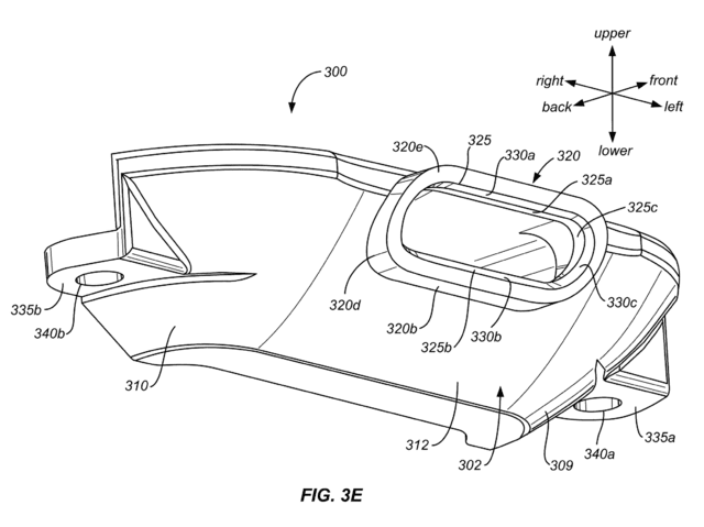
FIGS. 3A-3G illustrate a connector trim ring or bracket 300 according to an embodiment of the present invention. FIGS. 3A-3D are front, back, top and bottom plan views, respectively, of bracket 300 according to an embodiment of the present invention. FIGS. 3E-3F are front and back perspective views, respectively, of bracket 300 according to an embodiment of the present invention. FIG. 3G is a partial cutaway back perspective view of bracket 300 according to an embodiment of the present invention. Bracket 300 as shown in FIG. 3A includes a front face 302 having lower and upper front face portions. The upper portion include left and right portions 304, 306 and a center portion 308 extending between the left and right portions 304, 306. The lower portion includes left and right portions 309, 310 extending between a center portion 312. As shown in FIG. 3A, and more clearly in FIGS. 3C and 3E, left and right upper and lower portions 304, 306, 309, 310 may have a rounded curvature. FIGS. 3B-3D show that bracket 300 also includes a back face 314 and upper and lower opposing faces 316, 318.
US9955988(ETHICON INC [US])
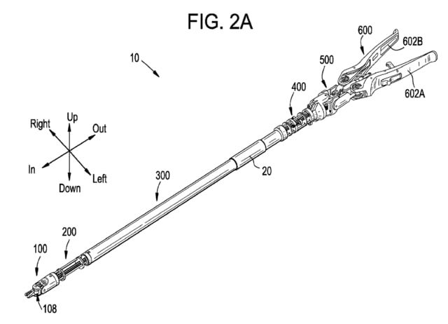
For convenience of description, surge is sometimes described herein as translational movement in an “in” direction or an “out” direction, heave is sometimes described as translational movement in an “up” direction or a “down” direction, and sway is sometimes described as translational movement in a “left” direction or a “right” direction. Likewise, roll is sometimes described herein as rotation about a longitudinal axis, pitch is sometimes described as pivoting in the up direction or the down direction, and yaw is sometimes described as pivoting in the left direction or the right direction. An exemplary mapping of the in, out, up, down, left, and right directions to a surgical device is shown in FIG. 2A. This mapping is generally used throughout the description that follows, for example to describe the relative positioning of components of the device (e.g., “upper,” “lower,” “left,” “right”) or to describe direction of movement within a particular degree of freedom (e.g., “leftwards,” “rightwards,” “up,” “down”). This terminology and the illustrated mapping are not intended to limit the invention, and a person having ordinary skill in the art will appreciate that these directional terms can be mapped to the device or any component thereof in any of a variety of ways.


※コメント投稿者のブログIDはブログ作成者のみに通知されます