


WO2015021391
"Fig. 2 is a simplified block diagram of the wearable electronic device of Fig. 1 .
図2は、図1のウェアラブル電子デバイスの簡略ブロック図である。
With reference to Figs. 1 and 2, the wearable electronic device 100 may include a hub 102 or computing center.
図1及び図2を参照すると、ウェアラブル電子デバイス100は、ハブ102又はコンピューティングセンターを含み得る。
In embodiments where the electronic device 100 is configured to be worn by a user, the device 100 may include one or more straps 104, 106 that may connect to opposite sides of the hub 102.
電子デバイス100が、ユーザによって装着されるように構成される実施形態では、デバイス100は、ハブ102の対向側部に接続することが可能な、1つ以上のストラップ104、106を含み得る。
Each of the straps 104, 106 may wrap around a portion of a wrist, arm, leg, chest, or other portion of a user's body to secure the hub 102 to the user.
ストラップ104、106のそれぞれを、手首、腕、脚、胸、又はユーザの身体の他の部分に巻き付けることにより、ハブ102をユーザに固定することができる。
For example, the ends of each of the straps 104, 106 may be connected together by a fastening mechanism 108.
例えば、ストラップ104、106のそれぞれの端部を、締結機構108によって一体に接続することができる。
The fastening mechanism 108 can be substantially any type of fastening device, such as, but not limited, to, hook and loop, magnetic fasteners, snaps, buttons, clasps or the like.
締結機構108は、限定するものではないが、フックアンドループ、磁気締結具、スナップ、ボタン、留め金などの、実質的に任意のタイプの締結デバイスとすることができる。
However, in one embodiment, such as the one shown in Fig. 1 , the fastening mechanism 108 is a buckle including a prong 134 or element that can be inserted into one or more apertures 1 12 in the second strap 106 to secure the first and second straps 104, 106 together. "
しかしながら、図1に示すものなどの一実施形態では、締結機構108は、第2のストラップ106内の1つ以上の開口112内に挿入することにより、第1のストラップ104と第2のストラップ106とを一体に固定することが可能な、爪部134又は要素を含む、バックルである。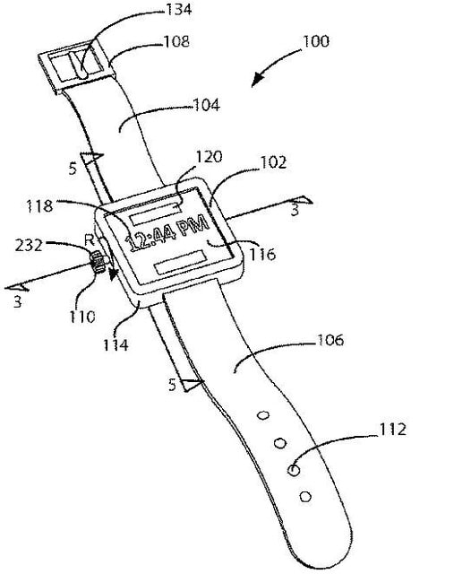
WO2014118520
"The outer end 136b of the arm 136 includes a yoke 143 within which the roller 138 is rotatably mounted on an axle 143a.
アーム136の外端部136bは、内部でローラ138が車軸143aに回転自在に取り付けられたヨーク143を含む。
Note that the roller 138 is mounted in the yoke 143 so that the roller 138 does not protrude significantly below the underside of the arm 136.
なお、ローラ138は、ヨーク143内において、アーム136の下面よりも下方に大きく突出しないように取り付けられる。
The maximum outward travel of the arm 136 is limited by a pair of catches 144 defined by opposed walls 145 on either side of the arm 136.
アーム136の最大外向き移動は、アーム136の両側の対向する壁部145によって定められる1対の爪部144によって制限される。
The catches 144 are engageable with a stop 146 that is provided on the chassis 4.
爪部144は、シャーシ4に設けられた停止部146と係合することができる。
In this embodiment, the roller 138 provides minimal rolling resistance to the mobile robot as it travels over a surface.
この実施形態では、ローラ138が、移動ロボットが表面上を移動する時に移動ロボットに最低限の転がり抵抗を与える。
However, the roller could also be replaced by an alternative such as a skid or runner if it was considered suitable for a particular mobile robotic application."
しかしながら、特定の移動ロボット用途に適している考えられる場合には、このローラをスキッド又はランナーなどの代替手段に置き換えることもできる。
US9618029
"Referring to FIGS. 4-14, one example of the disclosure relates to system 220 for use in covering portion 212 of fastener 210 (shown in FIG. 3).
図4~14を参照して説明すると、本開示の一実施例は、留め具210(図3に示す)の部分212を使用するシステム220に関する。
System 220 includes a tooth 230 and a cap 250. Cap 250 includes an interior 252, an exterior 254, a wall 256, a base 258, and a seal 260 coupled to base 258.
システム220は、歯230及びキャップ250を有する。キャップ250は、内部252、外面254、壁部256、基部258、基部258に連結されたシール260を有する。
Interior 252 is at least partially delimited by wall 256 and base 258.
内部252の少なくとも一部は、壁部256及び基部258によって規定されている。
Interior 252 further includes a surface 262 and pawls 264 on surface 262 that positively engage tooth 230.
内部252は、面262と、面262に設けられており、歯230にポジティブに係合する爪部264とをさらに有する。
As used herein, the terms “positively engage” and/or “positive engagement” means requiring more force to remove than to install.
本文書において、「ポジティブに係合する」及び/又は「ポジティブな係合」とは、取り付けよりも取り外しの方が大きな力を要することを意味する。
Moreover, tooth 230 includes a tapered surface 232, and at least one port 270 is formed in wall 256."
歯230は、テーパー面232を有しており、壁部256には少なくとも1つの開口270が形成されている。
WO2012164303
"The tensioner attachment portion 9 (shown in Figures 5a and 5b) comprises a tab 15 having two ribs 16 extending across the width of the tab 15. The ribs have a greater width and depth than the tab 15. The tab also comprises two apertures 17.
(図5a及び図5bに示される)テンショナの取付部分9は、爪部15の幅を横切って延びる二つのリブ16を有する爪部15を備える。リブは、爪部15より大きい幅及び深さを有する。爪部はまた二つの孔17を含む。
The tab 15, ribs 1 6 and apertures 17 are provided to assist in attachment of the tensioner 3 to the tensioner end 2 of the head strap.
爪部15、リブ16及び孔17は、ヘッドストラップのテンショナ端2へテンショナ3を取り付けるときに役立つように設けられている。
The head strap is formed of plastic material e.g. silicone which is molded (e.g. injection molded or compression molded) around the attachment portion 9 as shown in Figures 6a and 6b.
ヘッドストラップは、図6a及び図6bに示されるように取付部分9の周りに成形される(例えば射出成形又は圧縮成形される)プラスチック材料(例えばシリコーン)で形成される。
By providing the ribs and apertures, if is possible to ensure a firm bond between the molded plastic material of the tensioner end 2 and the attachment portion 9. Figure 3 shows how the cross bars 13, 14 are embedded within the plastics material forming the tensioner end 2."
リブ及び孔を設けることによって、テンショナ端2を形成するプラスチック材料と取付部分9との間の結合を堅固にすることが可能である。図3は、テンショナ端2を形成するプラスチック材料内にクロスバー13、14が埋め込まれている様子を示す。
WO2013096644
"In the embodiment of Fig. 4, slidable gap filling element 338A prevents one or more projections 334 on second member 330 from being withdrawn from one or more recesses 344 disposed in first member 300, thereby interlocking second member 330 to first member 300, as tension applied to removal member 336A withdraws first member 300 and second member 330 proximally to an initial position within a lumen of lock element 350. As pawl 352 of lock element 350 engages a tapered proximal end of first member 300, the tension required to withdraw removal member 336A increases and may be sensed by the operator who may then confirm that the anchoring member is properly positioned before proceeding. The skilled artisan will recognize that the shapes of the pawl 352 and the one or more recesses 344 may be complimentary, and that minor changes or adjustments to the shapes may enhance and/or optimize certain functionalities of these features within the scope of the present disclosure. For example, the pawl 352 and/or the one or more recesses 344 may have a curved or rounded shape, a block-like square or rectangular shape, a triangular shape, or other polygonal or complex geometry, and/or combinations thereof. "
図4の実施形態では、摺動可能な填隙要素338Aは、取外し部材336Aに適用された張力が第1の部材300および第2の部材330を錠止要素350のルーメン内部の初期配置状態へと基端方向に引き寄せるとき、第2の部材330の1つ以上の突起334が第1の部材300に配置された1つ以上の凹部344から引き出されるのを防止することにより、第2の部材330を第1の部材300に連動させる。錠止要素350の爪部352は第1の部材300のテーパ状基端部に係合するため、取外し部材336Aを引き寄せるのに必要な張力は増大し、かつ、手術者によって感知され、手術者はその後、手順を進める前に固定化部材が適切に位置決めされていることを確認することができる。当業者であれば、爪部352および1つ以上の凹部344の形状は相補的であってもよいこと、ならびに、形状の小さな変更または調整により、本開示の範囲内で上記特徴のある種の機能性についての増強および最適化のうち少なくともいずれかを行うことができることを認識するであろう。例えば、爪部352および1つ以上の凹部344のうち少なくともいずれか一方は、湾曲形状もしくは丸い形状、ブロック様の正方形状もしくは長方形状、三角形状、またはその他の多角形状もしくは複雑な幾何学形状、およびこれらの組み合わせを有することができる。
latch, hook, nail


※コメント投稿者のブログIDはブログ作成者のみに通知されます