EP3767785(JP)
[0011] Figs. 1 and 2 illustrate a hybrid-type hydraulic excavator 1 according to the embodiment.
【0011】
図1および図2は、実施の形態によるハイブリッド式の油圧ショベル1を示している。
As illustrated in Fig. 1 , the hydraulic excavator 1 includes an automotive crawler-type lower traveling structure 2, an upper revolving structure 4 rotatably mounted on the lower traveling structure 2 through a revolving device 3, and a working mechanism 5 of an articulated structure provided on a front side of the upper revolving structure 4 and performing excavating operation and the like.
図1に示すように、油圧ショベル1は、自走可能なクローラ式の下部走行体2と、下部走行体2上に旋回装置3を介して旋回可能に搭載された上部旋回体4と、上部旋回体4の前側に設けられ掘削作業等を行う多関節構造の作業装置5とを備えている。
The lower traveling structure 2 and the upper revolving structure 4 constitute a vehicle body of the hydraulic excavator 1.
下部走行体2および上部旋回体4は、油圧ショベル1の車体を構成している。
The lower traveling structure 2 includes hydraulic motors 2A, 2B for performing traveling operation.
下部走行体2は、走行動作を行うための油圧モータ2A,2Bを備えている。
The hydraulic motor 2A is provided on the left side of the lower traveling structure 2.
油圧モータ2Aは、下部走行体2の左側に設けられている。
The hydraulic motor 2B is provided on the right side of the lower traveling structure 2.
油圧モータ2Bは、下部走行体2の右側に設けられている。
The revolving device 3 includes a hydraulic motor 3A for performing revolving operation.
旋回装置3は、旋回動作を行うための油圧モータ3Aを備えている。
The lower traveling structure 2 is a crawler type illustrated herein, but may be a wheel type.
なお、下部走行体2としてクローラ式を例示したが、ホイール式でもよい。
EP3742000(JP)
[0014] As depicted in FIG. 1 , a hydraulic excavator 100 includes a lower track structure 1C, an upper swing structure 1B mounted for swinging motion on the lower track structure 1C, and a front implement 1A attached for pivotal motion in upward and downward directions to the front side of the upper swing structure 1B.
【0014】
図1に示すように、油圧ショベル100は、下部走行体1Cと、この下部走行体1C上に旋回可能に搭載された上部旋回体1Bと、この上部旋回体1Bの前側に上下方向に回動可能に取り付けられたフロント装置1Aとを備えている。
The lower track structure 1C is driven to travel by a traveling motor not depicted, and the upper swing structure 1B is driven to swing by a swing motor not depicted.
下部走行体1Cは図示しない走行モータによって走行駆動され、上部旋回体1Bは図示しない旋回モータによって旋回駆動される。
US2020318322(JP)
[0032] FIG. 1 is a side view schematically showing a construction of hydraulic excavator 1 based on an embodiment.
【0015】
(第一実施形態)
図1は、実施形態に基づく油圧ショベル1の構成を概略的に示す側面図である。
FIG. 2 is a plan view of hydraulic excavator 1 shown in FIG. 1.
図2は、図1に示す油圧ショベル1の平面図である。
As shown in FIGS. 1 and 2, hydraulic excavator 1 in the present embodiment mainly has a travel unit 2 , a revolving unit 3 , and a work implement 4 .
図1,2に示されるように、本実施形態の油圧ショベル1は、走行体2と、旋回体3と、作業機4とを主に有している。
A main body of hydraulic excavator 1 is constituted of travel unit 2 and revolving unit 3 .
走行体2と旋回体3とにより、油圧ショベル1の本体が構成されている。
[0033] Travel unit 2 has a pair of left and right crawler belts 2 A.
【0016】
走行体2は、左右一対の履帯2Aを有している。
Hydraulic excavator 1 is constructed to be self-propelled as the pair of left and right crawler belts 2 A is rotationally driven.
左右一対の履帯2Aが回転駆動することにより、油圧ショベル1が自走可能に構成されている。
Revolving unit 3 is revolvably attached to travel unit 2 .
旋回体3は、走行体2に対して旋回自在に設置されている。
Revolving unit 3 mainly has a cab 5 , an exterior cover 6 , and a counterweight 7 . Cab 5 is arranged on a front left side of revolving unit 3 (a front side of the vehicle).
旋回体3は、キャブ5と、外装カバー6と、カウンタウェイト7とを主に有している。
WO2019152494
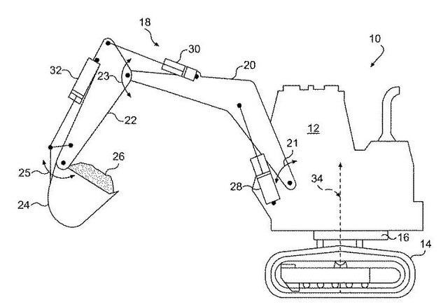
[0031] FIG. 1 is a simplified side view of an excavator that includes a platform 11, a boom 12, a stick 16, and a bucket 20.
【0022】
[0031]図1は、プラットフォーム(*上部旋回体)11、ブーム12、スティック16、およびバケット20を含む掘削機の簡略化された側面図である。

The boom 12 is pivotally coupled to the platform 11 at a pivot point 14, the stick 16 is pivotally coupled to the boom 12 at a pivot point 18, and the bucket 20 is pivotally coupled to the stick 16 at a pivot point 22.
ブーム12は、旋回軸14でプラットフォーム11に旋回可能に結合されており、スティック16は、旋回軸18でブーム12に旋回可能に結合されており、バケット20は、旋回軸22でスティック16に旋回可能に結合されている。
Hydraulic devices 24, 26, 28 are provided to move the boom 12, the stick 16, and the bucket 20.
ブーム12、スティック16、およびバケット20を動かすために、油圧装置24、26、28が設けられている。
The bucket 20 includes teeth 30 that may assist in digging.
バケット20は、掘削の助けとなり得るトゥース(*爪)30を含む。
The platform 11 includes a cab 31 supported on an undercarriage 32 that may include wheels or tracks to facilitate movement of the excavator over a worksite.
プラットフォーム11は、作業現場での掘削機の移動を容易にするために車輪または無限軌道を含み得る下部走行体32上に支持されたキャブ31を含む。
The platform 1 1 can be rotated about a generally vertical axis 35 by a hydraulic motor 33.
プラットフォーム11は、油圧モータ33によっておおむね垂直な軸35を中心に回転させることができる。
It should be appreciated that although this example includes a one-piece boom, embodiments described herein can be utilized with excavators having variable angle booms.
この例は一体型ブームを含むが、本明細書に記載される実施形態を、可変角度ブームを有する掘削機で利用できることを理解されたい。
Further, the excavator can be used with other implements or tools besides the bucket 20 such as augers, trenchers, compactcors, and the like.
さらに、掘削機を、バケット20の他に、オーガ、トレンチャ、コンパクターなどの他の器具または工具と共に使用することができる。
WO2010075105
In many different heavy equipment machines, an operator cab is supported by a frame of the machine with cab mounts.
【0002】
多くの異なる重機機械において、オペレータキャブは、キャブマウントを有する機械のフレームによって支持されている。
Cab mounts are available in many different forms and configurations and generally try to isolate the cab from the undercarriage of the machine so as to limit the vibrational impact experienced by the operator when the machine moves or performs work.
キャブマウントは、多くの異なる形態及び構成で利用可能であり、概して、機械が移動したり、又は作業を行ったりするときに操作者が被る振動衝撃を抑えるため、機械の下部構造体からキャブを隔離しようとするものである。
For example, with a loader traveling over rocky terrain, the chassis, undercarriage, and wheels/track of the loader may be jostled and bounced around considerably,
例えば、岩地を走行しているローダでは、ローダの車台、下部構造体、及び車輪/履帯が大きく方々に突き上げられたり、跳ね返ったりし得るが、
but as the cab is not fixedly mounted to the frame, the play afforded by the cab mounts lessens the effect of that motion on the operator.
キャブはフレームに固定的に取り付けられていないため、キャブマウントによって提供される遊びにより、操作者に対するこの動きの影響は小さくなる。
US7113105
As illustrated in FIG. 1, work machine 10 includes a housing 12 that may include a seating area for an operator.
【0013】
図1に示したように、作業機械10は、操作者用の着座領域を含み得るハウジング12を含む。
Housing 12 may be mounted on a swing assembly 16 that is configured to rotate or pivot housing 12 about a vertical axis 34.
ハウジング12は、垂直軸線34を中心にハウジング12を回転または旋回するように構成されるスイングアセンブリ16に装着し得る。
Swing assembly 16 may include a hydraulic actuator, such as, for example, a fluid motor or a hydraulic cylinder, that pivots housing 12 about vertical axis 34.
スイングアセンブリ16は、垂直軸線34を中心にハウジング12を旋回する例えば流体モータまたは油圧シリンダのような油圧アクチュエータを含んでもよい。
Pressurized fluid may be introduced to the hydraulic actuator of swing assembly 16 to move swing assembly 16.
加圧流体をスイングアセンブリ16の油圧アクチュエータに導入して、スイングアセンブリ16を移動し得る。
The direction and rate of the introduced flow of pressurized fluid governs the direction and velocity of movement of swing assembly 16.
導入される加圧流体流の方向および速度はスイングアセンブリ16の移動の方向および速度を制御する。
US2023117708(CATERPILLAR SARL [CH])
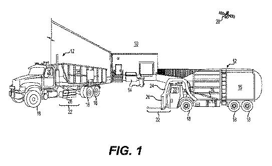
[0025] As illustrated in FIG. 4 , a working machine 10 like a hydraulic excavator is configured to include a machine body 11 comprising a lower traveling body 12 and an upper slewing body 13 provided on the lower traveling body 12 so as to be able to slew(*=slue: pivot, turn),
【0019】
図4に示されるように、油圧ショベル形の作業機械10は、機体11が、下部走行体12と、この下部走行体12に旋回可能に設けられた上部旋回体13とを備え、
and a working equipment 14 for various works and a counter weight 15 mounted on the upper slewing body 13 of the machine body 11 .
この機体11の上部旋回体13に、各種作業用の作業装置14、および、カウンタウエイト15が搭載されている。
In the illustrated example, the working equipment 14 is like a bucket, but is not limited to this, and may be the one equipped with a breaker or the like.
図示される例では、作業装置14は、バケット形であるが、これに限らず、ブレーカなどが搭載されたものでもよい。