EP3522133(JP)
[0004] In a case where the object detection device detects an object in the periphery of the work vehicle, for example, the periphery monitoring system outputs a warning sound to a passenger (for example, an operator) of the work vehicle.
【0004】
物体検出装置が作業車両の周辺の物体を検出したとき、例えば、周辺監視システムは、作業車両の搭乗者(例えばオペレータ)に向けて警報音を出力する。
When the warning sound is output in a case where the object is an obstacle affecting the operation of the work vehicle, the passenger of the work vehicle can recognize a state where an obstacle exists in the periphery of the work vehicle.
物体が作業車両の稼動に影響するような障害物である場合、警報音が出力されることにより、作業車両の搭乗者は、作業車両の周辺に障害物が存在することを認識することができる。
However, in a case where the work vehicle enters a building or performs a work inside the building,
しかし、作業車両が建屋の内部に進入したり建屋の内部で作業したりする場合、
the object detection device detects, for example, a wall surface of the building as an obstacle and outputs an unnecessary warning sound in a state where the obstacle does not exist in the periphery of the work vehicle or the passenger clearly recognizes a state in the periphery of the work vehicle.
作業車両の周辺に障害物が存在しない状況又は搭乗者が明らかに作業車両の周辺の状況を認識できている状況において、物体検出装置が、例えば建屋の壁面を障害物として検出することにより、不要な警報音が出力され、
As a result, the passenger feels troublesome.
搭乗者は煩わしさを感じることがある。
EP3438353(JP)
[0016] Fig. 1 to Fig. 12 show a first embodiment.
[0016] 図1ないし図12は、第1の実施の形態を示している。
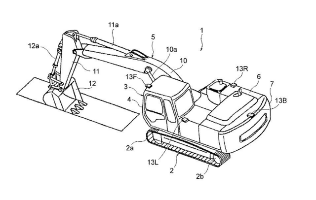
In Fig. 1 , a hydraulic excavator 1 that is a representative example of construction machines includes
図1において、建設機械の代表例である油圧ショベル1は、
an automotive lower traveling structure 2 of a crawler type,
走行可能なクローラ式の下部走行体2と、
an upper revolving structure 4 that is rotatably mounted on the lower traveling structure 2 through a revolving device 3,
該下部走行体2上に旋回装置3を介して旋回可能に搭載された上部旋回体4と、
and a working mechanism 5 that is tiltably provided in the front side of the upper revolving structure 4 in a front-rear direction.
該上部旋回体4の前,後方向の前側に俯仰動可能に取付けられた作業装置5とを含んで構成されている。
The lower traveling structure 2, the revolving device 3 and the upper revolving structure 4 configure a vehicle body of the hydraulic excavator 1,
下部走行体2、旋回装置3および上部旋回体4は、油圧ショベル1の車体を構成しており、
and the lower traveling structure 2, the revolving device 3, the upper revolving structure 4 and the working mechanism 5 configure a machine (construction machine).
下部走行体2、旋回装置3、上部旋回体4および作業装置5は、機械(建設機械)を構成している。
[0021] The upper revolving structure 4 is provided with
【0021】
上部旋回体4は、
a revolving frame 6 formed as a support structural body on the front side in the front-rear direction of which the working mechanism 5 is mounted,
支持構造体をなし前,後方向の前側に作業装置5が取付けられた旋回フレーム6と、
a housing cover 7 that accommodates an engine 10, a main pump 11, a pilot pump 12, a control valve device 14 and the like that are disposed on the revolving frame 6,
旋回フレーム6上に設けられたエンジン10、メインポンプ11、パイロットポンプ12、制御弁装置14等を収容する建屋カバー7と、

a counterweight 8 that acts as a weight balance to the working mechanism 5 and a cab 9 on which an operator boards.
作業装置5との重量バランスをとるカウンタウエイト8と、オペレータが搭乗するキャブ9とを備えている。
EP3041227(JP)
[0022] Hereafter, embodiments of the present invention will be described with reference to the attached drawings.
【0022】
以下、図面に基づいて本発明の実施の形態について説明する。
In Fig. 1 and Fig. 2 , an hydraulic excavator 1 is shown as an example of a working machine.
まず、図1及び図2に作業機械の一例としての油圧ショベル1の構成を示す。
In these drawings, the reference numeral 2 denotes a traveling structure having a crawler type traveling mechanism, the traveling structure 2 is rotatably connected to a swiveling structure 3.
図中において、2はクローラ式走行手段を有する走行体であって、走行体2には旋回体3が旋回可能に連結されている。
The traveling structure 2 has crawler 2a which is driven by sprocket 2b.
走行手段2は履帯2aを有し、履帯2aは駆動輪2bにより駆動されるものである。
[0023] An operator's cab 4 is mounted on the swiveling structure 3, an operator being boarded in the operator's cab 4 for performing operation of the machine.
【0023】
旋回体3には運転室4が設けられており、オペレータは運転室4に搭乗して機械を操作することになる。
A front working member 5 is positioned at the right side of the operator's cab 4 approximately with side by side relation.
土砂の掘削等の作業を行う作業手段として、フロント作業機5が設けられている。フロント作業機5は運転室4の右手において、ほぼ並ぶような位置に設けられる。
In addition, a machine housing 6 and the like are mounted on the swiveling structure 3 at the rear side, eventually a counterweight 7 being placed at rear end.
さらに、旋回体3には、運転室4及びフロント作業機5の後方位置に建屋6等が設けられており、最後端部にはカウンタウエイト7が設置されている。
US2015204351(JP)
[0029] As shown in FIG. 8, the engine room 22 is covered with an engine room cover 26 that has a plurality of air inlet openings 26 a .
【0020】
エンジン室22は、図8に示すように複数の空気取入口26aが形成された建屋カバー26で覆われており、

A diesel engine 27 is housed in the engine room 22 . Also, a heat exchanging unit 28 is placed in the vicinity of the diesel engine 27 .
その内部にはディーゼルエンジン27が収容されていると共にその近傍には熱交換器ユニット28が設置されている。
The diesel engine 27 and the heat exchanging unit 28 are fixedly secured on the swing body frame 21 with tightening bolts (not shown) and engine mounting parts (not shown).
このディーゼルエンジン27と熱交換器ユニット28は、旋回体フレーム21上に図示しない締結ボルトやエンジンマウントによって支持固定されている。
EP2172626(JP)
[0015] The hydraulic excavator 1 is largely constituted by a vehicular lower structure 2, an upper revolving structure 4 which is revolvably mounted on the vehicular lower structure 2 through a revolving mechanism 3, and a working mechanism 5 liftably supported at the front of the upper revolving structure 4.
この油圧ショベル1は、自走可能なクローラ式の下部走行体2と、該下部走行体2上に旋回装置3を介して旋回可能に搭載された上部旋回体4と、該上部旋回体4の前側に俯仰動可能に設けられた作業装置5とにより大略構成されている。
In this instance, the vehicular lower structure 2 and the upper revolving structure 4 constitute an automotive vehicle according to the present invention.
ここで、下部走行体2と上部旋回体4は本発明に係る走行体を構成している。
[0046] Denoted at 33 is a housing cover which is built on the revolving frame 6 for housing the engine 8, control valve 16 and ureal water tank 28.
また、33はエンジン8、制御弁16、尿素水タンク28等を覆うように旋回フレーム6上に設けられた建屋カバーである。
This housing cover 33 includes
この建屋カバー33は、
a plural number of openable side cover portions 33A to 33D which covered both sides can be opened to uncover,
両側面を開,閉可能に覆う複数の側面カバー部33A~33Dと、
and a front cover portion 33E positioned in the right forward portion which openably and closacly cover the ureal water tank 28 and the like.
右前部に位置して尿素水タンク28等を開閉可能に覆った前側カバー部33Eとを有している。


