


Article 46
Incorrect Translation of the International Application
国際出願の正確でない翻訳
If, because of an incorrect translation of the international application, the scope of any patent granted on that application exceeds the scope of the international application in its original language, the competent authorities of the Contracting State concerned may accordingly and retroactively limit the scope of the patent, and declare it null and void to the extent that its scope has exceeded the scope of the international application in its original language.
国際出願が正確に翻訳されなかつたため、当該国際出願に基づいて与えられた特許の範囲が原語の国際出願の範囲を超えることとなる場合には、当該締約国の権限のある当局は、それに応じて特許の範囲を遡及して限定することができるものとし、特許の範囲が原語の国際出願の範囲を超えることとなる限りにおいて特許が無効であることを宣言することができる。
WO2007081752
Techniques for computing position and phase information, resulting in much lower computational requirements without any significant loss of accuracy, are described.
精度を著しく失うことなく必要な計算量をかなり減らせる、位置およびフェーズ情報を計算する手法について説明する。
For example, described techniques can reduce computational requirements significantly - e.g., by reducing nominal dynamic range requirements dramatically (by tens of bits).
例えば、説明されている手法は、例えば、公称ダイナミックレンジ要件を劇的に(数十ビットほど)下げることにより必要計算量を著しく減らせる。
Considering the variety of possible chroma positions that may be used in base and enhancement layers, it is desirable to find a solution providing proper positioning of resampled chroma samples relative to luma samples.
ベースレイヤおよびエンハンスメントレイヤで使用されうる様々な可能な色度位置を考えると、輝度サンプルに関する再サンプリングされた色度サンプルの適切な位置決めを行う解決策を見つけることが望ましい。
Accordingly, described techniques allow adjustments to be made to calculate positions for video formats with different relationships between luma and chroma positions.
したがって、説明されている手法を使用することで、輝度位置と色度位置との間の異なる関係によりビデオ形式に対する位置を計算するように調節を行うことができる。
WO2007028940
The invention aims to provide efficient full colour from an electroluminescent source. Full colour comprises at least three primaries, typically red, green and blue, but the invention is not so limited.
本発明の目的は、エレクトロルミネッセンスソースにより高効率のフルカラーを与えることである。フルカラーは、少なくとも3つの原色、代表的には、赤色、緑色及び青色を有するが、本発明はそれらに限定されるものではない。
The invention is equally applicable to four primaries such as RGB+ White or RGB+Cyan
本発明は、例えば、RGB+白色又はRGB+シアン色のような4原色に同様に適用可能である。
Current products using the CBW approach are inefficient.
CBW方法を用いる現在の製品は非効率的である。
CBW方法を用いる現在の製品は非効率的である。
Typical radiance outputs, measured in W/sr/rn2, can be less than 10% of the original optical emission before filtering.
典型的な放射輝度出力は、W/sr/m2を単位として測定され、フィルタリングする前には、オリジナルの光発光の10%以下である。
典型的な放射輝度出力は、W/sr/m2を単位として測定され、フィルタリングする前には、オリジナルの光発光の10%以下である。
Commercially available organic dyes when used with phosphors would typically have poor UV stability and chromaticity position.
市販されている有機色素は、蛍光体と共に用いられるとき、典型的には、低い紫外線安定性及び色度位置を有する。
市販されている有機色素は、蛍光体と共に用いられるとき、典型的には、低い紫外線安定性及び色度位置を有する。
EP3373207
[0010] FIG. 1 illustrates an exploded view of an example of a circular printed memory device 100. The circular printed memory device 100 may include
図1は、円形印刷メモリ装置100の一例の分解図を示す。円形印刷メモリ装置100は、
a base substrate 102, a plurality of bottom electrodes 1041- 104n(hereinafter also referred to individually as a bottom electrode 104 or collectively as bottom electrodes 104), a ferroelectric layer 106 and a single top electrode 108.
ベース基板102と、複数の下部電極1041~104n(以下、個別に下部電極104またはまとめて下部電極104とも呼ぶ)と、強誘電体層106と、単一の上部電極108とを含み得る。
In one embodiment, the base substrate 102, the bottom electrodes 104, the ferroelectric layer 106 and the single top electrode 108 may be layered on top of one another.
一実施形態では、ベース基板102、下部電極104、強誘電体層106および単一の上部電極108は、互いに重なり合って積層されてもよい。
WO2018148624
In this three-roll configuration, a first substrate 734 and at least a second substrate 736 may be conveyed on an absorbent article manufacturing line in the machine direction.
この3ロール構成では、第1の基材734及び少なくとも第2の基材736は、吸収性物品製造ライン上で機械方向に搬送されてもよい。
The first and second substrates may have different or the same cross-directional widths, basis weights, and/or materials, fibers, and/or hydrophobic/hydrophilic properties, for example, as described herein.
第1及び第2の基材は、例えば、本明細書に説明するように、異なるか又は同一の横断方向幅、坪量、及び/又は材料、繊維、及び/又は疎水性/親水性特性を有し得る。
The first and second substrates may be overlapped with each other to form an area of overlap between the first and second substrates.
第1及び第2の基材は、互いに重なり合って、第1の基材と第2の基材との間に重なり合う区域を形成してもよい。
The first and second substrates may be conveyed on the third roll 712 between the weld anvils 716 and the ultrasonic welding unit 722
第1及び第2の基材は、第3のロール712上で溶接アンビル716と超音波溶接ユニット722との間で搬送されてもよく、
such that ultrasonic welds 735 may be formed between the first and second substrates in the area of overlap to cause them to join together.
それにより重なり合う区域において第1の基材と第2の基材との間に超音波溶接部735が形成されて、それらを共に接合させてもよい。
The joined laminate of the first and second substrates may then be conveyed through a first nip 715 formed between the first roll 708 and the third roll 712.
第1及び第2の基材の接合された積層体は、次いで、第1のロール708と第3のロール712との間に形成された第1のニップ715を通して搬送されてもよい。
The first distal portions 724 of the first plurality of projections 720 of the first roll 708 may aperture at least the area of overlap between the first and second substrates.
第1のロール708の第1の複数の突起部720の第1の遠位部分724は、少なくとも第1の基材と第2の基材との間の重なり合う区域に孔を開けてもよい。
The first and second substrates 734, 736 may travel partially around the first roll 708, with the apertures in the laminate still being engaged with the first plurality of projections 720 of the first roll 708,
第1及び第2の基材734、736は、積層体の孔が第1のロール708の第1の複数の突起部720と依然として係合した状態で、第1のロール708の周りを部分的に移動し、
and be conveyed through a second nip 717 formed between the first roll 708 and the second roll 710.
第1のロール708と第2のロール710との間に形成された第2のニップ717を通して搬送されてもよい。
WO2016100177
Similar to FIGS. 1A-1C, FIG. 7 is illustrated for clarity purposes with the top and bottom sides of the envelope 502 being substantially spaced apart (i.e., with a sidewall joining them), and with the locking sheets 510 being substantially spaced apart from one another.
図1A~図1Cと同様に、図7は、包被502の上面及び下面が実質的に離間し(即ち、それらを結合する側壁によって)、ロック用シート510が互いに実質的に離間していることを明確にするために示されている。
However, it should be understood that this illustration is used merely to better and more clearly show how the locking sheets 510 can overlap one another and can be positioned in the chamber 504.
しかし、この図は、ロック用シート510がどのように互いに重なり合ってチャンバ504内に配置され得るかを、より良くより明確に示すためにのみ用いられていることを理解されたい。
In reality, the apparatus 500 can appear much flatter, having a sheetlike or plate-like configuration.
実際には、装置500は、シート状又は板状の構成を有して、より平坦に見え得るものである。
WO2018152169
[0037] Referring now to FIG. 5, an example lamination system 130B for applying a polymer material 122 to a flexible glass web 112 is schematically illustrated. The lamination system 130B includes at least two rollers 134A, 134B.
ここで図5を参照すると、フレキシブルガラスウェブ112に高分子材料122を施すための例示の積層システム130Bが概略示されている。積層システム130Bは、少なくとも2つのローラ134A、134Bを備える。
The polymer material 122 and the flexible glass web 112 are fed between the rollers 134A, 134B to laminate the polymer material 122 to the flexible glass web 112.
高分子材料122およびフレキシブルガラスウェブ112は、ローラ134A、134Bの間に供給されて、高分子材料122がフレキシブルガラスウェブ112に積層される。
In some embodiments, the laminated flexible glass web 112 may then be rolled into a spool. Any known or yet-to-be-developed lamination process may be utilized.
いくつかの実施の形態において、積層されたフレキシブルガラスウェブ112は、次に、スプールに巻き付けられることがある。どの公知のまたはまだ開発されていない積層過程を利用してもよい。
[0039] After application of the polymer material 122 to the glass substrate or web 111, the coated glass substrate/web 111 may then be severed into a plurality of laminate substrates having one or more desired shapes.
高分子材料122がガラス基板またはウェブ112に施された後、被覆されたガラス基板/ウェブ112は、次いで、1つ以上の所望の形状を有する複数の積層基板に切断することができる。
積層基板:Google Advanced Patent Search/rudwig/当ブログ(非JP)
laminate substrate: 4170/2/2
laminated substrate: 8590/0/1(貼り合わせ基板)
stacked substrate: 1290/0/0
multilayer substrate: 22400/3/2
multilayerは「多層」と訳される場合も多いと思う。
追記13FEB2021
Intel/Microsoft/Corning
laminate substrate: 1069/0/193
laminated substrate: 152/16/218
stacked substrate: 101/0/34
multilayer substrate: 646/5/82
WO2012078522
Helix Device Incorporating Sensors
螺旋装置内蔵用センサ(*センサを内蔵した)
In another preferred embodiment of the present invention, the helix device may comprise one or more sensors so as to indicate conditions such as temperature, pressure, radiation, position and/or any other status for diagnostic or therapeutic treatment during the procedure.
本発明のもう1つの好ましい実施形態では、螺旋装置は、温度、圧力、放射能、位置、及び/又は処置中の診断的又は療法的処置についてのその他の状況のような状態を表示させるために1つ又は複数のセンサを備えていてもよい。
WO2007078738
[0062] Although hard drives with a storage capacity of hundreds of gigabytes have recently become cost- effective for incorporation in user equipment, such as set top boxes (STB) , the available storage space on recording device 114 may still limit local recording of programs.
数100ギガバイトの記憶容量を備えたハードドライブは、セットトップボックス(STB)等のユーザ機器内蔵用として、最近は費用効率の高いものとなってきているが、記録装置114上の利用可能な記憶容量は、依然として、プログラムのローカル記録を制限する場合がある。
However, situations may arise where VOD assets may not be always available, for example, because a connection between the VOD client and the VOD server has insufficient bandwidth, for example, at certain peak traffic times, or tends to be otherwise unreliable.
しかしながら、例えば、VODクライアントとVODサーバとの間の接続が、一定のピークトラフィック時間等に、不十分な帯域幅を有している、あるいは不安定であるため、VODアセットが常に利用可能ではない場合が生じ得る。
It may then be advantageous to give priority to recording the scheduled broadcast instead of the equivalent VOD content.
したがって、同等のVODコンテンツの代わりに、スケジューリングされた放送の記録を優先させることは有利となり得る。
Since the available transmission bandwidth and access times to the VOD server can be determined by both the headend and the user equipment, the system may decide dynamically to either locally record the broadcast or a pointer to the equivalent VOD asset.
利用可能な伝送帯域幅およびVODサーバへのアクセス時間は、ヘッドエンドとユーザ機器との両方によって判断可能であるため、システムは、放送または同等のVODアセットへのポインタのいずれかをローカルに記録するように動的に決定してもよい。
US2006038088
[0019] According to the present invention, a linkage 40 is provided to house the electrical lines 36/38.
発明によると、リンク機構40は電線36/38内蔵用として備え付けられている。
The linkage 40 is convertible between a retracted condition when the slat 16 is in the retracted position (FIG. 2A) and an extended condition when the slat 16 is in the extended position (FIG. 2B).
本リンク機構40は、スラット16が格納位置にある(図2A)格納状態と、スラット16が伸長位置にある(図2B)伸長状態との間で転換可能である。
The linkage 40 accommodates the repeated extension and retraction of the slat 16 and protects the electrical lines 36/38 from the adverse slat environment.
リンク機構40は、スラット16の伸長および格納を繰返し調節することにより、電線36/38を不都合なスラットの環境から保護する。
This environment can include, for example, hot/cold temperatures, high altitudes, and humidity extremes, excessive vibration, and accelerated wind speeds, as well as exposure to fluids, salt spray, sand and dust.
この環境としては、例えば高温/低温、高空、極度の湿度、過度の振動、および上昇する風速、さらには流動体への暴露、塩風、および粉塵が含まれる。
WO2014078698
[0123] The elongate members 1 102a may generally pivot on or around the donut- shaped member 1 107a, which may facilitate collapsing and expanding the frame 1 100a, for example, for loading and deploying the device to/from a delivery system.
長尺部材1102aは、ドーナツ形部材1107aの上又はその周りで回動でき、それによって、例えば送達系への器具の装填及び/又は送達系からの器具の留置のために枠1100aの伸縮を容易にできる。
For example, each of the elongate members 1 102a may generally pivot around the donut shaped member 1 107a.
例えば、長尺部材1102aの各々は、概ねドーナッツ形部材1107aの周りを回動できる。
WO2018118471
[0004] For many adhesive or lens potting applications, it is necessary to bond together materials (substrates) of different coefficients of thermal expansion.
多くの接着剤またはレンズ注封用途について、熱膨張係数が異なる材料(基体)を互いに結合する必要がある。
In these applications, the adhesive or potting material must allow for the expansion and contraction of the two different substrates as the temperature changes yet still maintain the adhesion of the two substrates together.
これらの用途において、その接着剤または注封材料は、温度が変化するときに2つの異なる基体の伸縮を可能にし、それでも、2つの基体の互いの接着を維持しなければならない。
This requires the use of a soft, low modulus, low Tg rubbery type material. The ability to formulate materials that cure to soft, compliant, rubber-like solids and yet still have low outgassing after cure is very difficult.
これには、軟質で、低モジュラスの、低Tgのゴム類材料を使用する必要がある。軟質で柔軟なゴム状固体に硬化し、それでも、硬化後にガス放出の少ない材料を配合することは、非常に難しい。
This is especially true if the cured material also has to have excellent thermal, oxidative, and hydrolytic stability.
このことは、硬化した材料が、優れた熱安定性、酸化安定性、および加水分解安定性も有さなければならない場合、特に当てはまる。
WO2014179425
Materials incorporated in a product: Materials that are pre -bonded in a product are taken as a prepared sample.
製品に組み込まれる材料:製品にあらかじめ接着される材料が、調製サンプルとして使用される。
To perform the T-peel test, the bonded material is cut from the product, if possible.
T型剥離試験を行うために、可能な場合には、接着材料を製品から切断する。
However, if the adherend (wrinkled film in this case), and/or adherent are joined to other materials in a face-to-face configuration, the face-to-face configuration between the adherend and the other material or adherent and the other material should be maintained.
しかし、被着体(この場合はしわの寄ったフィルム)及び/又は接着体が他の材料に向かい合わせの形体で接合されている場合には、被着体と他の材料又は接着体と他の材料との間の向かい合わせの形体を保たなければならない。
Removal of the materials from the product should be done to preserve the integrity of the materials (e.g. , adherend and adherent should not be permanently deformed or should not be debonded from each other).
製品からの材料の除去は、材料の一体性を保持するように行わなければならない(例えば、被着体及び接着体を恒久的に変形させたり又は相互から剥離させたりしてはならない)。
Before loading the samples for T-peel test, the receiving and engaging surfaces should be separated approximately 1 -5 mm to initiate the peeling.
T型剥離試験のためにサンプルを取り付ける前に、受容及び嵌合表面を約1~5mm離して、剥離を開始しなければならない。
The portion of the sample including the adherend is the receiving sample 812, and the portion of the sample including the adherent is the engaging sample 822.
被着体を含むサンプル部分は受容サンプル812であり、接着体を含むサンプル部分は嵌合サンプル822である。
The receiving sample 812 and engaging sample 822 should each extend at least 25 millimeters beyond the bonded portion of the samples such that the proximal edge 840 of the receiving sample 812 and the proximal edge 842 of the engaging sample 822 can be easily placed in the test instrument' s grips.
受容サンプル812の近位縁840及び嵌合サンプル822の近位縁842を試験計器のグリップ内に容易に配置できるように、受容サンプル812及び嵌合サンプル822はそれぞれ、これらサンプルの接着部分を少なくとも25ミリメートル超えて延びていなければならない。
The T- peel test should be performed on the bonded materials as described in the method below.
T型剥離試験は、以下の方法の部分に記載されているように、接着材料の上で行わなければならない。
A skilled artisan should recognize that peel angle can affect the peel force.
剥離角度は剥離力に影響を及ぼす可能性があることは、当業者には理解されよう。
During peeling, the peel angle should be maintained around 180 degrees (i.e., adherent and adherend pulled directly away from each other).
剥離中、剥離角度は約180度に維持すべきである(すなわち、接着体と被着体が互いに反対方向に引っ張られる)。
Furthermore, if the adherent or adherend are elastomeric, the adherent or adherend must be backed with a similar sized sheet of 2 mil (0.05 mm) PET film in order to prevent stretching of the tested substrate.
更に、接着体又は被着体がエラストマーである場合には、試験基材の伸縮を防ぐために、同じ寸法のシートの0.05mm(2mil)のPETフィルムで接着体又は被着体を裏打ちしなければならない。
WO2017152075
[0063] In some embodiments, nanoscale conductive additives can also be present in the printing compositions. These additives can desirably provide further structural reinforcement and reduce shrinkage during metal nanoparticle consolidation.
ある実施形態では、印刷組成物にはナノスケールの導電性添加剤も存在し得る。これらの添加剤は、望ましくは、さらなる構造補強をもたらし、金属ナノ粒子固結中の収縮を抑制することができる。
Moreover, inclusion of nanoscale conductive additives can increase electrical and thermal conductivity values that can approach or even exceed that of the corresponding bulk metal following nanoparticle consolidation.
さらに、ナノスケールの導電性添加剤を含めることで、ナノ粒子固結後の対応するバルク金属の電気伝導率及び熱伝導率の値に達し得るか又はこれを超え得るように電気伝導率及び熱伝導率の値を高めることが可能となる。
In some embodiments, the nanoscale conductive additives can have a size in at least one dimension ranging between about 1 micron and about 100 microns, or ranging between about 1 micron and about 300 microns.
ある実施形態では、ナノスケールの導電性添加剤の少なくとも1方向における粒径は、約1ミクロンから約100ミクロン又は約1ミクロンから約300ミクロンであってもよい。
Suitable nanoscale conductive additives can include, for example, carbon nanotubes, graphene, and the like.
適切なナノスケールの導電性添加剤は、例えば、カーボンナノチューブやグラフェンなどを含み得る。
When present, the printing compositions can contain about 1% to about 10% nanoscale conductive additives by weight, or about 1% to about 5% nanoscale conductive additives by weight
本明細書では、印刷組成物は、約1重量%から約10重量%のナノスケールの導電性添加剤、又は、約1重量%から約5重量%のナノスケールの導電性添加剤を含み得る。
Additional substances that can also optionally be present include, for example, flame retardants, UV protective agents, antioxidants, carbon black, graphite, fiber materials (e.g., chopped carbon fiber materials), and the like.
任意選択的に存在し得る追加の物質としては、例えば、難燃剤、UV防護剤、酸化防止剤、カーボンブラック、グラファイト、ファイバ材料(例えばチョップド炭素繊維材料)などが挙げられる。
WO2015176016
Each time the energy source melts a layer of material the heat is conducted through the built part underneath resulting in expansion upon heating and contraction upon cooling of the underlying material due to the material's inherent thermal expansion properties.
エネルギー源が材料の層を溶融するたびに、熱は下の構築された部分を通じて伝導し、結果として加熱の際に膨張し、下層の材料の冷却の際に材料の固有の熱膨張特性によって収縮する。
Additionally, the molten layer produced during irradiation of a new layer forms metallurgical bonds with the underlying layers and then undergoes contraction upon cooling.
The bonds between the new layer and the underlying layers constrain the contraction of the alloy at the interface and thereby induce compressive stresses in the new layer.
さらに、新しい層の照射中に製造された溶融した層は、下層の層との金属学的な結合を形成し、したがって冷却の際に収縮を受ける。
新しい層と下層の層との間の結合は、界面における合金の収縮を抑制し、それによって新しい層内に圧縮応力を誘起させる。
The material must therefore be capable of withstanding cracking due to the stresses induced during the thermal cycling caused by the cyclic energy source in layerwise construction.
したがって、材料は、層状構成における繰り返すエネルギー源によって引き起こされる熱サイクル中に誘起される応力による割れに耐えることができなければならない。
WO2004094321
[0064] Figure 5 shows a laminated sheet 32 having a surface layer 34, a core layer 36, and a bottom layer 38, where the core layer 36 is sandwiched between the surface layer 34 and the bottom layer 38.
図5は、表面層34、コア層36、および底層38を有する積層板32であって、コア層36が表面層34と底層38との間に挟まれている積層板32を示している。
The surface layer 34, core layer 36, and bottom layer 38 may be single layers, as illustrated in the figure, or may be made of sub-layers.
表面層34、コア層36、および底層38は、図示したように単層であっても、複数の副層から製造されていてもよい。
The surface layer 34 has a fusion-formed optical surface 40 that can serve as a basis for fabricating functional elements (not shown), such as TFTs, OLEDs, or color filters.
表面層34は、TFT、OLED、またはカラーフィルタなどの機能素子(図示せず)を製造するための基礎として働けるフュージョン成形された光学表面40を有する。
The fusion-formed optical surface 40 is untouched by a forming device, e. g. , uncontaminated by refractory material, and has a fire-polished surface quality.
フュージョン成形された光学表面40は、成形装置に触れない、例えば、耐火材料により汚染されず、ファイヤー・ポリッシュの表面品質を有する。
The bottom layer 38 is generally non-functional and does not necessarily have to meet the stringent requirements for the surface layer 34. The surface and bottom layers 34, 38 can be made very thin.
底層38は、一般に非機能性であり、表面層34の厳しい要件を必ずしも満たす必要はない。表面層34および底層38は非常に薄く製造することができる。
The core layer 36 can be made much thicker than the surface and bottom layers 34,38 and may have a higher section modulus than the surface and bottom layers 34, 38 so as to improve the overall structural integrity of the laminated sheet 32.
コア層36は、表面層34および底層38よりもずっと厚く製造でき、積層板32の全体の構造の健全性を改善するように表面層34および底層38よりも高い断面係数を有してもよい。
The core layer 36 can be made of a low thermal shrinkage material that will constrain the shrinkage of the laminated sheet 34 while undergoing cyclic thermal history.
コア層36は、周期的熱履歴を経ている間積層板32の収縮を抑制する低熱収縮材料から製造できる。
US9863256
[0018] 図1に示すように、少なくとも1つの実施形態では、翼10は、ガスタービンエンジン用のタービン翼10であってよく、
[0039] In at least one embodiment, as shown in Figure 1 , the airfoil 10 may be a turbine airfoil 10 for a gas turbine engine
外壁24により形成された全体として細長い中空翼26を備えていてよく、
and may include a generally elongated hollow airfoil 26 formed from an outer wall 24,
and having a leading edge 32, a trailing edge 34, a pressure side 36, a suction side 38, and inner endwall 40 at a first end 42
さらに前縁32と、後縁34と、正圧面36と、負圧面38と、第1端部42における内側端壁40と、
and an outer endwall 44 at a second end 46 that is generally on an opposite side of the generally elongated hollow airfoil 26 from the first end 42
この第1端部42とは全体として細長い中空翼26のほぼ反対側の第2端部46における外側端壁44と、
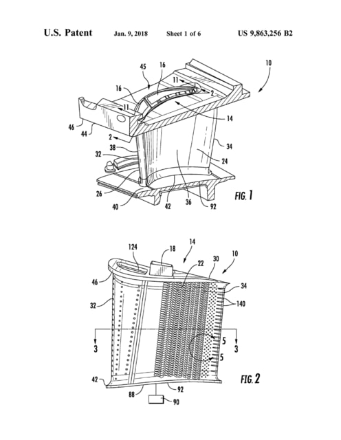
and a cooling system 14 positioned within interior aspects of the generally elongated hollow airfoil 26.
全体として細長い中空翼26の内側面に位置する冷却システム14とを有している。
(*以下文献番号不明)
the guide tube lying opposite the coupling apparatus,
前記結合装置(12)の反対側にある前記ガイドチューブ(14)
a world facing surface that is convex and opposite the eye-ward facing surface
前記目方向接面の反対側に位置する凸状の世界接面
The body has a pivot end on an opposite side of the screw axis from the injector axis
本体部(60)は、ねじ軸(160ax)の、インジェクタ軸(110ax)とは反対側に、ピボット端(64)を有する
a compressor impeller attached to the shaft opposite the turbine
タービンと反対側にて前記軸に取り付けられたコンプレッサインペラ
The inductor loop is placed on the side of the copper and magnetic material structure opposite to the lossy material
インダクタループは、銅及び磁性材料の構体における損失性材料とは反対側に位置する
The driver electronics layer is deployed in spaced-apart relation to the active layer and opposite the waveguide.
ドライバ電子機器層は、活性層に対して間隔を空けた配置関係で、導波路の反対側に展開される。
the thrust application mechanism 33 is arranged on a back surface side of the movable sheave 32 in the axial direction, that is, on an opposite side of the fixed sheave 31 with the movable sheave 32 being interposed therebetween.
推力付与機構33は、軸線方向で可動シーブ32の背面側、すなわち可動シーブ32を挟んで固定シーブ31とは反対側に配置されている
an electrical connector having opposite first and second ends
反対側に配置された第1の端部及び第2の端部
今日の12時40分~13時、医療従事者への敬意を込めた都内上空フライトがあるようで、楽しみです。
当ブログの例文について
本ブログの「特許英語散策」等題した部分では、英語の例文を管理人の独断と偏見で収集し、適宜訳文・訳語を記載しています。
訳文等は原則として対応日本語公報をそのまま写したものです。私個人のコメント部分は(大抵)”*”を付しています。
訳語は多数の翻訳者の長年の努力の結晶ですが、誤訳、転記ミスもあると思いますのでご注意ください。


