US9422981(NAKANISHI METAL WORKS CO [JP])
[0318] As shown in FIG. 32, when the swing swaging process is performed on the column part 5 from the two-dot chain line to the solid line, the material of a swage margin I plastically flows to the surrounding region to form the flange portion.
図32に示すように、二点鎖線から実線まで揺動加締めされると、加締め代Iの部分の材料が、そのまま周辺部分へ塑性流動して、フランジ部分を形成すると考えられる。
[0319] Therefore, the volume of the crushed swage margin I and the volume of the flange portion are equal. Accordingly,
したがって、押し潰される加締め代Iの部分の体積とフランジ部分の体積が等しくなるので、
by setting in advance thickness J of the swaged portion (flange portion) and the area of the flange portion, protrusion height H from the large-diameter ring 6 can be determined by volume calculation.
加締め部(フランジ部)の厚さJ及びフランジ部の面積を予め設定することにより、体積計算によって、大径リング6からの突出高さHを算出することができる。
US2017194722(YAZAKI CORP [JP])
In the linking portion 3220 B linking the terminal body 3211 and the wire connecting body 3219 to each other with the fastening force working between the crimping pieces 3224 and 3225 ,
【0042】
加締め片224,225同士の締結力で端子本体211と電線接続部本体219とを連結する連結部220Bは、
the linking strength can be adjusted by adjusting the fastening force through adjustment of a burring diameter d1 and a crimping margin d2 in the burring crimped portion between the crimping pieces 3224 and 3225 .
加締め片224,225同士のバーリング加締め部分におけるバーリング径d1や加締め代d2を調整して締結力を調整することで、連結強度を調整することが可能とされている。

In other words, in the terminal fitting 3200 B, among the linking portions 3220 A and 3220 B linking the terminal body 3211 and the wire connecting body 3219 to each other, the linking portion 3220 B has the linking strength adjusting function.
つまり、端子金具200Bは、端子本体211と電線接続部本体219とを連結する連結部220A,220Bのうちの連結部220Bが、連結強度調整機能を有している。
US8967093(HONDA MOTOR CO LTD [JP])
[0062] In the production process of the cooling system 20 of this embodiment, when the flow path forming member 30 is inserted into the expanded pipe portion 21 a ,
【0035】
本実施形態の冷却装置20の製造工程において、拡管部21aの中に流路形成部材30を挿入したとき、
as shown in FIG. 4, the distal end edge 21 ae of the expanded pipe portion 21 a projects by a predetermined dimension (h) further towards the distal end side of the expanded pipe portion 21 a than the distal end face 31 of the flow path forming member 30 .
図4に示すように、拡管部21aの先端縁21aeが、流路形成部材30の先端面31よりも拡管部21aの先端側に、所定寸法(h)だけ突出した状態となる。
In this way, by adopting the construction in which the distal end edge 21 ae of the expanded pipe portion 21 a projects further towards the distal end side than the distal end face 31 of the flow path forming member 30 , a crimping amount of the distal end edge 21 ae is ensured.
このように、拡管部21aの先端縁21aeが流路形成部材30の先端面31よりも先端側に突出している構造であることで、先端縁21aeの加締め代が確保されている。

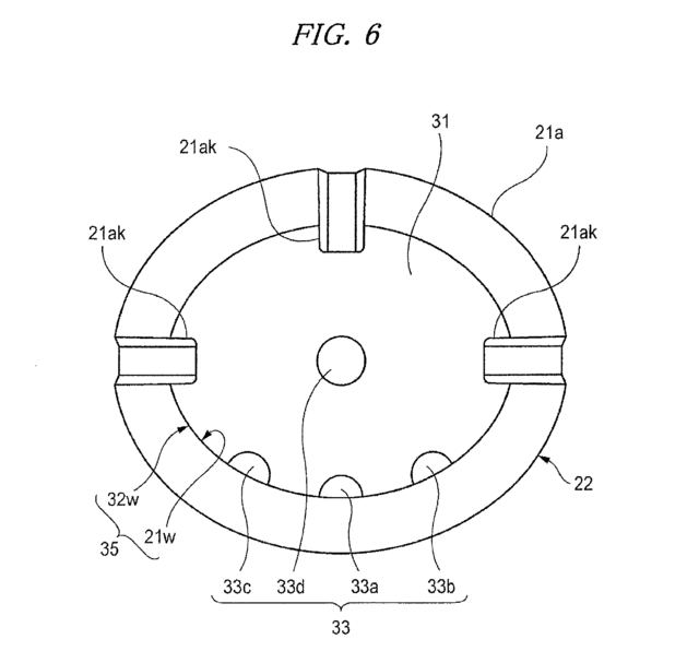
Consequently, it is extremely easy to form the locking portions 21 ak by crimping part of the distal end edge 21 ae radially inwards of the distal end portion 22 as shown in FIGS. 3 and 6.
したがって、先端縁21aeの一部を、図3および図6に示すように、先端部22の内径方向に加締めて係止部21akを形成することが極めて容易である。
US8631718(NILES CO LTD [JP])
[0011] As shown in FIG. 10C, the caulking process portion 117 is caulked in an edge portion of the bore portion 119 with a predetermined caulking margin to form a caulking portion 121 to the detent plate 113 , coupling the cylindrical member 111 to the detent plate 113 by caulking.
【0008】
図10(c)のように、前記加締め加工部117を所定の加締め代で前記穴部119の縁部に加締めて前記ディテント・プレート113に対する加締め部121を形成し前記円筒状部材111及びディテント・プレート113を加締め結合する。

[0012] The above caulking process is executed by a punch as shown in FIG. 11 and FIG. 12. FIG. 11 is a perspective view showing the punch, FIG. 12A is a front view showing the punch, and FIG. 12B is a cross section taken in the direction of arrows on line XIIb-VIIb of FIG. 12A.
【0009】
前記加締め加工は、図11,図12のようなパンチにより行われる。図11は、パンチの斜視図、図12(a)は、パンチの正面図、(b)は、(a)のXIIb-XIIb矢視断面図である。


