It is said that a 7 MHz dipole will carry 21 MHz in triple harmonics. It is a common knowledge.
But in reality, there are few stations that can get 21 MHz on a 7 MHz dipole without a tuner. But in fact, there are very few 7MHz dipole stations where 21MHz is successfully transmitted without a tuner.
If you want to get both 7 MHz and 21 MHz If you want to get both 7MHz and 21MHz, you can use a multiband antenna with a trap coil, or you can use separate elements for each band and share the same feed.
When I consulted with the local station, they told me that they had succeeded by changing the angle of the inverted V. I see.
After searching the Internet, I found a way to deal with this problem.
Even if you bring the lowest point to around 7.050MHz, in many cases, the lowest point of 21MHz will be the uppermost point. In many cases, the lowest point of 21MHz falls at the top, outside the band, and the SWR becomes high inside the band. The SWR in the band is high. (For calculation purposes, 21.150MHz should be the lowest point because it is a triple harmonic. )
There are two ways to deal with this.
One is to hang a whisker on the element about 3.5 meters from the power feed.
The other is to put a coil of several turns at 3.5 meters from the edge of the element. It's as simple as a few turns of dipole wire.
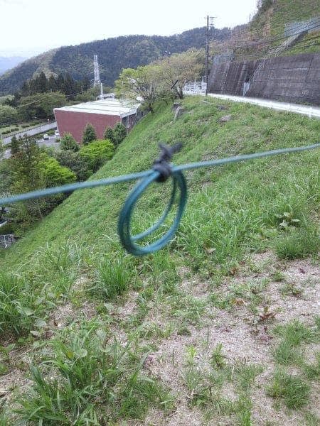
My antenna is an ultra-thin vinyl wire, so if I put a whisker in the middle of it, it would most likely get damaged there and break, so I tried the latter method of winding the wire of the element a few small times to make a coil.
According to the website, it was as simple as winding a 3.5 cm diameter loop four times and securing it tightly with a vinyl tie.
I tried it right away.
First of all, I measured the current condition. Maybe because I didn't use a balun, it had a V-shaped characteristic, but it was full size and had plenty of bandwidth. The 21MHz was far out of the band, with its lowest point around 21.75MHz. The SWR was about 1.5. The SWR was about 1.5. I used an antenna analyzer for the measurement.
I coiled the dipole with the elements at 3.5m from each end of the dipole. The total length will be shorter. Here is the measurement again.
The lowest point came up around 7.260MHz. SWR was 1.0, 21MHz. The lowest point of the Z coil is around 21.70MHz, not much change.
This time, I extended the folded end to extend the total length by 15 to 20 cm.
Then, the lowest point dropped to around 7.130MHz, and the 21MHz was 21.45MHz. 1 MHz dropped to about 21.45 MHz. This is a good sign. This was a good sign.
When I extended the total length by another 10 cm, the lowest point dropped to 7.060 MHz. The lowest point was 7.060 MHz, and 21 MHz was around 21.20 MHz. This is the best condition.
Now it is a dipole antenna that can be used for both 7 and 21MHz. The 21MHz has a little gain.
The photo was taken with the background in focus. (^^)
After the adjustment, I was so happy that I brought FT-817 under the antenna. I succeeded in communicating with Ishigaki Island.
When I finished, I felt that I made up for the shortening of the total length by extending the turnaround. The overall length was adjusted to 7MHz, and the coil was adjusted to 21MHz. It seems to have worked.
If you're having trouble getting 21MHz on a 7MHz (full size only) dipole, you should definitely try this.
Additional note
The shortening coil (also called extension coil) works best in the current belly. The area around 3.5m from the end of the coil is the current belly for 21MHz, and the area with less current distribution for 7MHz, so you can make this kind of adjustment.
Here, I put a coil in the current belly of the harmonic band, and re-adjusted the overall length to lower the tuning frequency on one side.
You can do the opposite by putting the coil in the lower current part of the harmonic band.
The current distribution is zero at the tip, maximum at 1/4 wavelength, zero again at 1/2 wavelength, maximum at 3/4 wavelength, and zero again at 1 wavelength.
The voltage distribution is the opposite of this. It is easy to get electrocuted at the tip of the antenna or near the feeding part of a voltage fed antenna, so be careful.


