


自分が今使っているのは、ベバストのAirTop2000STの同等性能品(中国製)でして、基本的取り付け方法はベバストと同じでした。
最近、そのWebasto社 から 最新型の”AirTop2000STC”(STでは無い、STCですので注意)が登場して、これも以前と設置方法は同じなのだろうか?なんて思って、検証してみることにしました。
AirTop2000STCは、 日本で一時期売られていたAirTop EVO2000(日本だけのオリジナル) にも変わる新型で、
これに、伴い ベバスト正規品のマルチコントローラ(タイマー機能含む)が選択できようになって販売されました。
日本には、日本オリジナルのベバコンというのが有りましたが、その以上の物が正規品として出てきたという感じです。
ST及びEVO2000からの変更がもう一つあって、それが燃料ポンプ(DP40)。
新型となって、高地での運用に正規対応したという点があります。
*注意 :スタンダードタイプという特段高地スイッチ機能を省いて、価格を抑えた仕様もあるとのこと。
ちなみに、新型コントローラは、普通の温度コントロールしか出来ないSmartControlと、タイマー機能等を持つ、MultiControl(HD)という2種類があり、外観が全く同じなので紛らわしいのですけど、HDの方はコントローラユニットの縁取りが銀色のメッキなのですぐ判ります。

で~だ、その最新型の2000STCのインストールマニュアル(設置取りつけ説明書)をwebastoからダウンロードして、どんな風にして取り付けるのか?を何回かに分けて説明してみようかと思っています。
時々、僕みたいなへそ曲がり男みたいに、”自分で取り付けてみたい!”という方もおられると思いますので、 そうした方達の参考になればと思っています。
ちなみに僕の使っている中国製のWebasto同等品ですが、全くといって良いほど設置方法は同じで、これは自分で車に取りつけました。
元々、ベバストのST型OEMですから。
さて、さっそく翻訳&説明に移りますけど、ベバスト社のインストールマニュアルを見ると、かなり余計な能書きも多く、なので重要点だけを記事にして行きたいと思います。
3 Installation
設置
3.1.Air Top 2000 STC installation situation
設置条件
NOTE:
Check the given conditions for installation in the respective type of vehicle.
インストールのための必要条件に車が合っているか?をまず確認すること。
3.2.Installation location
The heater may be installed both in the interior or on the exterior of the vehicle.
When using the vehicle in normal road traffic, the heater may only be installed with a contact guard to prevent contact if it is located within the reach of the driver.
If installed on the exterior, ensure that the heater is fitted in a position where it is protected from splash water and spray.
The heater must be installed in such a way that no water can enter the heater when the vehicle is driven through water conforming to the permissible fording level.
The openings for the combustion air inlet, the exhaust gas outlet and the fuel pipe must be sealed. The seal designed and supplied for this purpose must be used.
(See Fig. 3).
ごたごた書いて有りますが大したことは書いて有りません。
まとめると、ヒーターは内部と外部に設置が可能という事。
内部設置は置くところに注意して、必要ならガード(熱機器なので)しろという程度です、
外部設置に関しては、水のかからない処に取りつけするようにと書いてあり、実際に車体の下回り等に取り付ける場合、雨水の跳ね上げや、道路冠水で本体が浸かるような場所を避けねばなりません。
跳ね石なども有りますから、ヨーロッパ本国では必要に応じて専用ケースを使う事が多いようです。
燃焼吸気と特に燃焼排ガス、燃料配管は接続部を確実して、漏れが無いように! とされていて、至極当たり前のことが書いてある? です、ハイ!
3.3.Heater installation
ヒーター設置
When installing the Air Top 2000 STC heater, tighten the M6 nuts to a torque of 6 Nm +1.
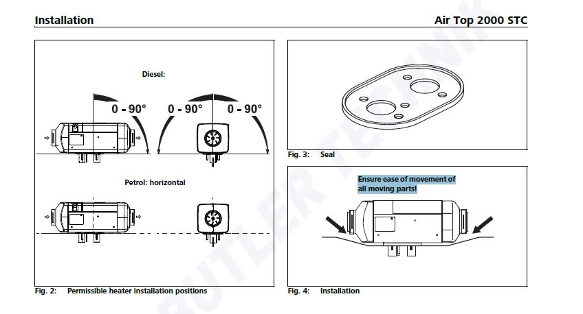
The installation dimensions and space requirements for service access are shown in the installation drawing (Fig. 1). The specified horizontal and axial angles of inclination must not be exceeded (Fig. 2).
A seal (Fig. 3) must be fitted between the heater and the vehicle body. The seal must be replaced each time the heater is reinstalled. The support surface for the heater base must be flat. The seal can compensate for unevenness of max. 1 mm.
ヒーターを取り付けるときはナットを6N-m(ニュートンメーター)のトルクで締めるとあります。
まあ、下に敷いているラバーパッキンが潰れるような馬鹿力でない程度の力で、しっかり締めればOKというトルクです。
パッキンその物は消耗品で、ヒーターを取り外す度に交換する必要があります。
このラバーパッキンは1mm程度の取り付け面の起伏やでこぼこまで対応可能と記載があります。
ATTENTION:
After installation check that the casing is not in contact with any part of the boat's body. Failure to do this may result in the heating air fan blocking.
取り付ける際に、本体が何かに当たるような処は避けよという事。
下の図を見ての通り、ヒーター本体は出来るだけ水平に、横取り付けは出来る限り避ける。 特にガソリン仕様は厳守です。
軽油仕様の方も基本的には同じですが、少しだけ条件が緩く、しかしながらホットエアの出口側(図の白い矢印がホットエアの流れ)が、下になるような角度が増すほど好ましくなく。 垂直取りつけに至ってはほぼOUTです。
その真逆はもちろん駄目ですので、注意。
*これは着火失敗などが有った際、燃料が吸気パイプ側に逆流して流れてきてしまう可能性が有る事からなのですけど、ホットエアの吹き出し口が下の場合は逆流しにくく、漏れてもその先が燃焼室なので、燃焼室で着火すれば燃えてしまう事と、燃焼空気が流れていく経路の関係でもそうなっています。
同じ様に、横置きも、その角度が増すほど好ましくなく(真横は完全にOUT)駄目という事です。
4Type label
設置の後に適切な位置にキット付属の”注意書きや案内ラベル”を張り付けろという内容なので省略
5Installation example
設置例 下の図を参照。
1Control element (コントローラー)
2Heater ヒーター
3Fuse ヒューズ
4Tank extracting device 燃料取り出しスタンド
5Fuel filter (accessory)燃料フィルター(アクセサリーなので必要に応じて)
6Fuel pumpヒーターの燃料ポンプ
7Exhaust silencer (accessory) 排気マフラー(アクセサリーなので必要に応じて)
8Combustion air intake line 吸気パイプ
9Combustion air intake silencer (accessory) 吸気パイプサイレンサー(アクセサリーなので必要に応じて)
10Maximum permissible fording level (車両の許されている冠水時最大深さ)

6Hot air system
ホットエア・システム
NOTE:
it is not permitted to integrate the heater into the vehicle's air circulation system.
A temperature sensor, which measures the room temperature, is mounted on the inside of the control unit. The required interior temperature is selected at the control element. The heating capacity is adapted automatically to the heating requirements of the room.
Both recirculation and fresh air modes are permitted.
Care must be taken for fresh air mode to ensure that the cold air is taken from an area protected from splash water and spray and in such a way that no water can enter the heater when the vehicle is driven through water conforming to the permissible fording level.
ヒーターの温度センサーは、本体内部のコントロールモジュールに取り付けられていて、それが検出した温度をもとにヒーターは運転されます。
*外部温度センサーを取りつけた場合はそちらが優先となり温度検出します
なので、ホットエアーが出ているそのすぐ真横に、空気の取り入れ口が有るような構成の仕方をすると、狭い範囲でエア循環(ホットエアーショート)することになり、性能が十分に発揮できません。
ヒーターを車体外部に取り付けた場合は、外部の水などが各部に吸い込まれないように適切に配管をしなければなりません。

NOTE:
For fresh air mode, a room temperature sensor must be installed in the area to be heated.
The inside diameter of the main section of the hot air duct should be 60 mm.
NOTE:
Only materials that can permanently withstand temperatures of at least 130 °C are to be used for the hot air duct. The hot air opening is to be positioned such that heat-sensitive parts are not damaged.
ホットエアーの配管は内径60mmで、130度の高温(純正品なら問題ありません)に耐える物が必要で、ダクト配管周辺や、エア出口に熱に弱い物を置いたり、 可燃物を置くことは許されません。
ホームセンターのアルミダクトは耐熱性はともかくも、残念なことに径75mmです。
ATTENTION:
注意
Every reasonable precaution should be taken in positioning the heater to minimize the risk of injury and damage to personal property.
Maximum pressure drop between the intake and pressure side of the hot air duct: 1.5 hPa
If this pressure drop is exceeded, the heater will reduce the heating capacity or shut down.
The hot air hose is to be secured at the connection points.
Avoid a short-circuit in the hot air flow when the heater is used in recirculated air mode.
ヒータへの空気取り入れ口と、ホットエアーの出口の気圧差が1.5hPa以下になると、ヒーターは燃焼熱量を減らすか、自動的にシャットダウンすると記載されてます。
まあ、上記のホットエア関連の記載ですが、普通に車内設置する分には条件的に特段難しい物ではありません。
注意点としては熱に弱い物をダクト配管周辺に置かない、もしくは遠ざけるのと、ホットエアの空気取り入れ口と、吐き出し口はできる限り離す設置方法を取るという事です。
7燃料配管
7Fuel supply
燃料供給
The fuel is taken from the vehicle's fuel tank or from a separate fuel tank. Refer to Chapter 7.1.4, "Pipe lengths and delivery head" for the permissible pressure at the fuel take-off point.
A notice, indicating that the heater must be shut down before refuelling, must be affixed to the filler neck.
燃料は車のタンク、もしくはセパレートの専用タンクを使います。
パイプの長さと各部の高さには注意してください。
7.1.Fuel lines
燃料ライン
7.1.1.Vehicles with carburetor engine
キャブレター仕様エンジン
The fuel may only be extracted with the special Webasto fuel extractor (Fig. 8) as close to the fuel tank as possible. The connection can be made either in the supply or return line, where the return line must extend almost to the bottom of the fuel tank.
The fuel extractor must be installed in such a way that any air or gas bubbles are automatically expelled towards the fuel tank (Fig. 8).
Fuel should be extracted in the vicinity of the engine as gas bubbles can form in the lines in this area due to the heat radiated from the engine. This can cause combustion problems.
ディーゼル及び、ガソリンのキャブレター仕様の車は、基本的にエンジン側からタンクへ戻る燃料ラインにTパイプを設置することで分岐できますが、その戻りラインのタンク内末端が、底に近いところまで行っているかどうか?を検討する必要があります。
*そうで無い場合、 燃料タンク内部の燃料が少なくなる事で、パイプ末端が油面より上に出てしまい、ヒーターのポンプが燃料を吸い出し出来ません。
*余り下まで配管があると、ヒータの燃焼で燃料が空になり、いざ車を走らせようとしたらエンジン始動できなくなる。
という様な事が起きる可能性も有りますが、FFヒーター自体がそんなに燃料を消費する物ではないので、そのまで心配する必要も無いと思います。
分岐は、エンジンに近い場所、もしくは熱を持ちやすい場所は避けるべきで、可能な限りタンク側に近いところから分岐してください。
理由は、エンジンが停止中でも、加熱しきったエンジン余熱で配管内の燃料がコポコポと沸騰(パーコレーション)する事が有り、その状態でヒーターを点火すると燃焼がうまくいかないトラブルが起きます。
尚、燃料取り出しスタンドパイプ使う方法もあります。その場合、タンク上部の適切な処に設置(メンテナンスホール蓋等ですが)してください。
7.1.2.Vehicles with fuel injection engine
インジェクション仕様車への取りつけ
When installing the heater in a vehicle with a fuel injection system, it is important to establish whether the fuel pump is located inside or outside the fuel tank.
If the fuel pump is located inside the fuel tank, fuel can only be extracted from the return line using the Webasto fuel extractor (Fig. 8). In this case it is necessary to ensure that the return line extends almost to the bottom of the fuel tank (otherwise the Webasto tank extracting device (Fig. 9, Fig. 10 and Fig. 11) can be used.
If the fuel pump is installed outside the fuel tank, the fuel connection can be made between the fuel tank and the fuel pump, again using only the Webasto fuel extractor (Fig. 8).
インジェクション車への取り付けは、特段慎重に検討して行わねばなりません。
重要注意事項:”ガソリン車”は、現在のところ、殆どがインジェクションシステムを採用していて、車両燃料タンク内ポンプによって配管ラインに高い圧力が掛かります。
その為、燃料配管経路を切断しての分岐配管をやたらとしてはなりません。
燃料リターンラインからの分岐は安全なので可能ですが、その場合も、取りつけに関して十分な検討が必要です。
そして必ず、車両燃料タンク周辺の、適切な位置から取り出してください。
燃料取りだしスタンドを使用することが可能ですが、殆どの場合は、 タンクの燃料ポンプユニット・アッセンブリーの空き部分(蓋部分)等に適切な穴開け加工等をしてそれを取り付けます。
全体的にですが、ガソリン仕様のFFヒーターの場合、ヒーター本体設置はともかくも、タンクから燃料配管を取り出す作業だけは、専門業者か知識をもつ人に任せるべきだと僕は思います
7.1.3.Extracting fuel with tank extracting device
Fuel must be extracted from the fuel tank or a separate tank (Fig. 8, Fig. 9 and Fig. 10). Separate fuel extraction has no influence on the pressure.
燃料タンクが、車両のタンクとは別の、専用タンク(ヒーターの為の単独設置)の場合は、燃料取りだしスタンドを使う等、してください。
全てにおいて共通事項として、スタンドパイプの吸い口が、底からある程度の距離(25mm程度)を置くように調整(カット等)が必要です。
そうでないばあい、タンク底に溜まる汚れや、ほこりなどを吸い込んだりして、ヒータトラブルの原因となります。
*必要に応じて燃料フィルターを使用のこと。
分岐パイプですが、分岐取り出し側を下にして、前後左右60度の範囲。

以上、その1でした。